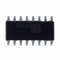
IRS2166DSPBF International Rectifier, IRS2166DSPBF Datasheet - Page 15

IRS2166DSPBF
Manufacturer Part Number
IRS2166DSPBF
Description
IC PFC/BALLAST/HALF BRDG 16-SOIC
Manufacturer
International Rectifier
Type
PFC/Ballast Controllerr
Datasheet
1.IRS2166DSPBF.pdf
(18 pages)
Specifications of IRS2166DSPBF
Frequency
40 ~ 46 kHz
Current - Supply
20mA
Current - Output
260mA
Voltage - Supply
12.5 V ~ 15.6 V
Operating Temperature
-25°C ~ 125°C
Package / Case
16-SOIC (3.9mm Width)
For Use With
IRPLLNR7 - KIT UNIV ELEC BALLAST FLUOR LAMP
Lead Free Status / RoHS Status
Lead free / RoHS Compliant
Available stocks
Company
Part Number
Manufacturer
Quantity
Price
Company:
Part Number:
IRS2166DSPBF
Manufacturer:
IR
Quantity:
9 182
www.irf.com
or
Step 4: Program Preheat Time
The preheat time is defined by the time it takes for the
capacitor on pin CPH to charge up to 12 V. An internal current
source of 3.6 µA (I
is therefore given as:
or
Step 5: Program Maximum Ignition Current
The maximum ignition current is programmed with the external
resistor R
determines the over-current limit of the ballast, which can be
exceeded when the frequency ramps down towards resonance
during ignition and the lamp does not ignite. The maximum
ignition current is given as:
or
PFC Design Equations
Step1: Calculate PFC inductor value:
R
f
PH
PH
=
=
t
C
I
R
L
PH
IGN
PH
CS
2
PFC
R
⎛
⎜ ⎜
⎝
CS
⋅
=
. 1
T
=
=
C
and an internal threshold of 1.20 V. This threshold
=
C
02
−
=
T
t
VCSTH
VCSTH
PH
PH
⎛
⎜ ⎜
⎝
⋅
(
⋅
. 1
VBUS
I
⎛
⎜ ⎜
⎝
C
R
⋅
⋅
CPH
IGN
1
. 0
02
. 0
2 e
CS
T
6 .
51
) flows out of pin CPH. The preheat time
385
R
⋅
⋅
+
T
f
C
+
6
⋅
1
2
PH
e
T
−
R
+
1
⋅
−
T
⋅
R
f
−
6
⋅
f
MIN
PH
2
PH
R
2892
⋅
PH
VAC
⋅
−
P
+
2892
OUT
⎞
⋅ ⎟ ⎟
⎠
1475
MIN
R
⋅
T
VBUS
⎞
⎟ ⎟
⎠
[H]
)
[Ω]
[Hz]
⎞
⎟ ⎟
⎠
[Ω]
⋅
[A]
[F]
VAC
[s]
(10)
(1)
(6)
(8)
(7)
(9)
MIN
2
(5)
⋅
η
where,
Step 2: Calculate peak PFC inductor current:
Note: The PFC inductor must not saturate at
the specified ballast operating temperature range. Proper
core sizing and air-gapping should be considered in the
inductor design.
Step 3: Calculate maximum on-time:
Step 4: Calculate maximum COMP voltage:
Step 5: Select zener diode D
Step 6: Calculate resistor R
Step 7: Calculate resistor ROC value:
VBUS
VAC
V
i
t
D
R
R
PK
ON
COMP
OC
SUPPLY
COMP
MAX
P
=
f
MIN
OUT
=
MIN
η
MAX
2
VAC
=
I
zener voltage
⋅
=
PFCMAX
2
=
=
=
=
=
=
VAC
VAC
⋅
2
minimum AC input voltage
MIN
P
DC bus voltage
Minimum rms AC input voltage
PFC efficiency (typically 0.95)
Minimum PFC switching frequency at
0
5
Ballast output power
⋅
OUT
t
IQCCUV
9 .
P
ON
OUT
_
MIN
⋅
2
MIN
E
PK
η
MAX
⋅
−
L
⋅
PK
IRS2166D(S)PbF
PFC
η
6
≈
SUPPY
+
COMP
V
10
COMP
value:
value:
MAX
[V]
[Ω]
[V]
[Ω]
[A]
[s]
i
PK
over
(3)
(4)
(5)
(7)
(6)
(2)
Page 15


