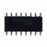
IRS2166DSPBF International Rectifier, IRS2166DSPBF Datasheet - Page 3

IRS2166DSPBF
Manufacturer Part Number
IRS2166DSPBF
Description
IC PFC/BALLAST/HALF BRDG 16-SOIC
Manufacturer
International Rectifier
Type
PFC/Ballast Controllerr
Datasheet
1.IRS2166DSPBF.pdf
(18 pages)
Specifications of IRS2166DSPBF
Frequency
40 ~ 46 kHz
Current - Supply
20mA
Current - Output
260mA
Voltage - Supply
12.5 V ~ 15.6 V
Operating Temperature
-25°C ~ 125°C
Package / Case
16-SOIC (3.9mm Width)
For Use With
IRPLLNR7 - KIT UNIV ELEC BALLAST FLUOR LAMP
Lead Free Status / RoHS Status
Lead free / RoHS Compliant
Available stocks
Company
Part Number
Manufacturer
Quantity
Price
Company:
Part Number:
IRS2166DSPBF
Manufacturer:
IR
Quantity:
9 182
www.irf.com
Electrical Characteristics
V
1000 pF, C
Supply Characteristics
Floating Supply Characteristics
PFC Error Amplifier Characteristics
PFC Control Characteristics
I
Symbol
COMP,SOURCE
CC
I
V
V
V
V
V
COMP,SINK
V
V
V
V
I
I
V
V
V
I
V
VBUSREG
QCCFLT
VBUSOV+
CC,RUN
COMPOH
VBUSOV-
QCCUV
I
I
COMPOL
I
ZXclamp
= V
I
CCUV+
UVHYS
CLAMP
V
CCUV-
QBS0
QBS1
BSUV+
LKVS
ZXHYS
t
BSUV-
QCC
WD
ZX
BS
= V
T
= 470 pF, T
V
threshold
V
threshold
V
UVLO mode V
Quiescent V
Fault quiescent V
V
V
Quiescent V
Quiescent V
V
threshold
V
threshold
V
OTA error amplifier output current sourcing
OTA error amplifier output current sinking
OTA error amplifier output voltage swing
(high state)
OTA error amplifier output voltage swing (low
state)
V
(guaranteed by design)
V
threshold
V
hysteresis
ZX pin positve edge triggered threshold
voltage
ZX pin comparator hysterisis
ZX pin clamp voltage (high state)
PFC watch-dog pulse interval
BIAS
CC
CC
CC
CC
CC
BS
BS
S
BUS
BUS
BUS
offset supply leakage current
supply undervoltage positive going
supply undervoltage negative going
supply undervoltage positive going
supply undervoltage negative going
supply undervoltage lockout hysteresis
current at RUN frequency
zener clamp voltage
=14 V +/- 0.25 V, V
internal reference voltage
over-voltage comparator positive going
over-voltage comparator negative going
A
=25 °C unless otherwise specified. See state diagram for MODE.
CC
BS
BS
CC
supply current
supply current
supply current
Definition
quiescent current
CC
supply current
CPH
=V
SD/EOL
=V
COMP
=V
CS
=V
Min
14.6
11.5
12.0
200
100
150
9.5
1.5
8.0
7.0
-45
3.9
4.1
4.0
1.5
5.7
20
---
---
---
---
---
---
---
BUS
=V
ZX
Typ
12.5
10.5
15.6
12.5
4.15
250
600
300
300
400
=0.0 V, R
2.0
4.3
5.0
9.0
8.0
-35
4.0
4.3
2.0
6.7
30
50
30
---
Max
13.5
11.5
16.6
10.0
13.0
500
900
400
500
500
3.0
5.1
9.0
-25
4.1
4.5
4.3
2.5
7.7
T
70
90
50
40
---
= R
PH
Units
= 39.2 kΩ, C
mA
mA
mV
mV
µA
µA
µA
µA
µA
IRS2166D(S)PbF
µs
V
V
V
V
V
V
V
V
V
Test Conditions
V
I
ZX
V
ZX
V
B
CC
V
CC
BS
MODE = FAULT
CC
= 0 V, V
= V
BS
= 5 mA, CT=COM
MODE = RUN
MODE = RUN
= 8 V, CT = COM
MODE=RUN
V
V
falling from 14 V,
falling from 14 V
V
COMP=2 V,
I
LO
rising from 0 V,
t
CT = COM
CT = COM
CT = COM
CT = COM
rising from 0 V
CC
VBUS
VBUS
off,PFC
CT=COM
CT=COM
COMP
S
V
V
= C
HO
HO
= HO = 600 V
= 10 mA
= 3.5 V
= 4.5 V
=4.0 V
=2 μs
= V
= V
COMP
HO
S
B
= C
= 2.0 V
PFC
=
Page 3


