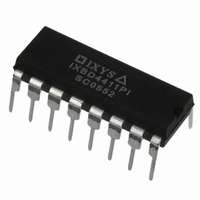
IXBD4411PI IXYS, IXBD4411PI Datasheet - Page 11

IXBD4411PI
Manufacturer Part Number
IXBD4411PI
Description
IC HIGH SIDE DRIVER 16DIP
Manufacturer
IXYS
Series
ISOSMART™r
Type
Isolated Half Bridge Driver Chip Setr
Datasheet
1.IXBD4410PI.pdf
(11 pages)
Specifications of IXBD4411PI
Configuration
High-Side
Input Type
Non-Inverting
Delay Time
110ns
Current - Peak
2A
Number Of Configurations
1
Number Of Outputs
1
High Side Voltage - Max (bootstrap)
1200V
Voltage - Supply
10 V ~ 20 V
Operating Temperature
-40°C ~ 85°C
Mounting Type
Through Hole
Package / Case
16-DIP (0.300", 7.62mm)
Product
Half-Bridge Drivers
Rise Time
100 ns
Fall Time
150 ns
Supply Voltage (min)
10 V
Maximum Power Dissipation
600 mW
Maximum Operating Temperature
+ 85 C
Mounting Style
Through Hole
Bridge Type
Half Bridge
Minimum Operating Temperature
- 40 C
Number Of Drivers
1
Output Current
2 A
Lead Free Status / RoHS Status
Lead free / RoHS Compliant
The nominal electrical specifications of
the transformer are as follows:
The recommended ferrite bead is Fair
Rite Products part number 2661000101,
which is manufactured by:
Fair-Rite Products Corp.
Wallkill, NY
Phone: (800) 836-0427
Web site: www.fair-rite.com
As seen in the application drawings
(Fig. 6, 9 and 12) a coupling capacitor
(22 nF) and a damping resistor (22 Ω)
are added in series with the primary
side of the transformer. The capacitor
will control the small amount of energy
needed to transfer the signal to the
companion driver. The resistor will
control the damping of the signal and
limit the peak transmitter output current.
The receiver is designed to operate
© 2004 IXYS All rights reserved
Open circuit inductance
(100 kHz; 20 mV):
Interwinding capacitance:
Primary leakage inductance: 0.1 µH
Turns ratio:
Primary-to-secondary isolation
(1min):
Core permeability (µ
i
):
1500 V~
3 µH
2 pF
125
6:2
Fig. 12: Transmitter/Receiver Waveforms
Fig. 11: Ferrite bead dimensions
over a wide common mode input range.
To reduce noise pickup, the receiver
has ±250 mV of input hysteresis.
If the signal is being distorted at the
transmitter, the transmitter is probably
running into current limit. A decrease in
the coupling capacitance or an increase
in the damping resistance should solve
this problem. The receiver operates
over a wide input range. The minimum
amplitude for one side of the receiver is
about 1 V and a maximum of about 3 V.
It is critical that there be no overshoot
on the transformer secondary wave-
form. Each signal should be slightly
overdamped. If significant overshoot
exists, the received signal may be
logically inverted. An increase of the
damping resistor will solve this problem.
DS96528E(05/04)
IXBD4410
IXBD4411
11


