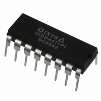
IXBD4411PI IXYS, IXBD4411PI Datasheet - Page 4

IXBD4411PI
Manufacturer Part Number
IXBD4411PI
Description
IC HIGH SIDE DRIVER 16DIP
Manufacturer
IXYS
Series
ISOSMART™r
Type
Isolated Half Bridge Driver Chip Setr
Datasheet
1.IXBD4410PI.pdf
(11 pages)
Specifications of IXBD4411PI
Configuration
High-Side
Input Type
Non-Inverting
Delay Time
110ns
Current - Peak
2A
Number Of Configurations
1
Number Of Outputs
1
High Side Voltage - Max (bootstrap)
1200V
Voltage - Supply
10 V ~ 20 V
Operating Temperature
-40°C ~ 85°C
Mounting Type
Through Hole
Package / Case
16-DIP (0.300", 7.62mm)
Product
Half-Bridge Drivers
Rise Time
100 ns
Fall Time
150 ns
Supply Voltage (min)
10 V
Maximum Power Dissipation
600 mW
Maximum Operating Temperature
+ 85 C
Mounting Style
Through Hole
Bridge Type
Half Bridge
Minimum Operating Temperature
- 40 C
Number Of Drivers
1
Output Current
2 A
Lead Free Status / RoHS Status
Lead free / RoHS Compliant
Chipset Overview
This ISOSMART
integrated circuits providing isolated
high- and low-side drivers for phase-
leg motor controls, or any other
application which utilizes a half bridge,
2- or 3-phase drive configuration. They
consist of two drive control inputs (INL
and INH) for two Power-MOSFET/IGBT
gate-drive outputs. Both inputs operate
from a common ground and are
activated by HCMOS compatible logic
levels. The low-side output operates
near input ground, while the high-side
output operates from a floating ground
that is nominally the source connection
of the high-side phase-leg power
device. Both outputs typically provide 2
A of transient current drive for fast
switching of the phase-leg power
device.
IXBD4410/IXBD4411
The full featured ISOSMART
chipset incorporates a IXBD4410 as
the low-side driver (Fig. 3) and a
IXBD4411 as the high-side driver (Fig.
2). When input "INL" is set to a positive
logic level, the low-side gate output
goes high (turns on); when "INH" is set
to a positive logic level, the high-side
gate drive output goes high. The high-
side IC is isolated from the low-side IC
by a magnetic barrier, across which the
turn on/off signal is transmitted to the
high-side gate drive. The IXBD4411
fault signal is also transmitted back to
the IXBD4410 driver via these
transformers. This isolation only
depends on the low cost communica-
tions transformer, which is designed to
withstand 1200 V or more.
There are two magnetic transmission
channels between the low- and high-
side IC's for bi-directional communi-
cation. One sends a signal from the
low-side IXBD4410 IC up to the high-
side IXBD4411 IC and the other sends
a signal back from the high-side to the
low-side IC. The signal that is sent up
controls the IXBD4411 gate-drive
output. The signal sent from the
IXBD4411 back to the IXBD4410
indicates a high-side fault has occurred
(overcurrent, or under-voltage of the
high-side +power supplies). This is
detected at the IXBD4410 driver and
sets "FLT" pin low, to indicate the high-
side fault.
The fault signal that is returned from
TM
chipset is a pair of
TM
driver
Fig. 2: IXBD4411, high-side driver block diagram
Fig. 3: IXBD4410, low-side driver block diagram
Fig. 4: Logic representation of IXBD4410 FLT signal
UV
UV
UV
UV
EE
DD
EE
DD
V
V
DD
DD
© 2004 IXYS All rights reserved
V
V
EE
EE
IXBD4410
IXBD4411
15
14
13
12
15
14
13
12


