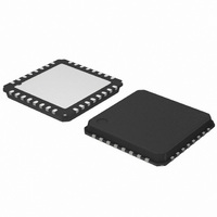
AMIS30624C6245RG ON Semiconductor, AMIS30624C6245RG Datasheet - Page 18

AMIS30624C6245RG
Manufacturer Part Number
AMIS30624C6245RG
Description
IC STEPPER DVR I2C 800MA 32-NQFP
Manufacturer
ON Semiconductor
Type
I2C Micro Stepping Motor Driverr
Datasheet
1.AMIS30624C6244RG.pdf
(56 pages)
Specifications of AMIS30624C6245RG
Applications
Stepper Motor Driver, 2 Phase
Number Of Outputs
1
Current - Output
800mA
Voltage - Supply
8 V ~ 29 V
Operating Temperature
-40°C ~ 165°C
Mounting Type
Surface Mount
Package / Case
32-VSQFP
Product
Stepper Motor Controllers / Drivers
Operating Supply Voltage
8 V to 29 V
Supply Current
800 mA
Mounting Style
SMD/SMT
Lead Free Status / RoHS Status
Lead free / RoHS Compliant
Voltage - Load
-
Lead Free Status / Rohs Status
Lead free / RoHS Compliant
Other names
766-1002-2
Available stocks
Company
Part Number
Manufacturer
Quantity
Price
Company:
Part Number:
AMIS30624C6245RG
Manufacturer:
ON Semiconductor
Quantity:
212
Company:
Part Number:
AMIS30624C6245RG
Manufacturer:
ON Semiconductor
Quantity:
1 850
Company:
Part Number:
AMIS30624C6245RG
Manufacturer:
ON Semiconductor
Quantity:
10 000
AMIS-30624
14.1.3. Position Periodicity
Depending on the stepping mode the position can range from –4096 to +4095 in half-step to –32768 to +32767 in 1/16
mode. One can project all these positions lying on a circle. When executing the command SetPosition, the position controller will
set the movement direction in such a way that the traveled distance is at a minimum.
Figure 9 illustrates that the moving direction going from ActPos = +30000 to TagPos = –30000 is clockwise.
If a counter clockwise motion is required in this example, several consecutive
movements, one could also use the command RunVelocity.
14.1.4. Hardwired Address HW
In Figure 10 a simplified schematic diagram is shown of the HW comparator circuit.
The HW pin is sensed via two switches S
connecting HW pin with a current to resistor converter. Closing S
R converter output is low, via the closed passing switch S
Closing bottom switch S
fed to the comparator. The output HW_Cmp will be high.
1 = R2GND
2 = R2VBAT 3 = OPEN
BOT
(DriveLS = 1) will sense a current to VBAT. The corresponding I
Figure 9: Motion Direction is Function on Difference Between ActPos and TagPos
HW
Figure 10: Simplified Schematic Diagram of the HW Comparator
TOP
+10000
0
-10000
and S
S
S
TOP
BOT
Rev. 4 | Page 18 of 56 | www.onsemi.com
BOT
. The DriveHS and DriveLS control lines are alternatively closing S
PASS_T
+20000
I
I
-20000
R
R
DriveHS
DriveLS
this signal is fed to the “R” comparator which output HW_Cmp is high.
TOP
(DriveHS = 1) will sense a current to GND. In that case the top I
TagPos = -30000
ActPos = +30000
S
S
PASS_T
PASS_B
Motion direction
R
th
SetPosition
"R"-Comp
COMP
HW_Cmp
R converter output is low and via S
Debouncer
LOGIC
commands can be used. For larger
32 μs
PC20060926.1
Debouncer
64 ms
th
micro-stepping
TOP
and S
State
High
Low
Float
PASS_B
BOT
,


