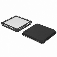
AMIS30624C6245RG ON Semiconductor, AMIS30624C6245RG Datasheet - Page 9

AMIS30624C6245RG
Manufacturer Part Number
AMIS30624C6245RG
Description
IC STEPPER DVR I2C 800MA 32-NQFP
Manufacturer
ON Semiconductor
Type
I2C Micro Stepping Motor Driverr
Datasheet
1.AMIS30624C6244RG.pdf
(56 pages)
Specifications of AMIS30624C6245RG
Applications
Stepper Motor Driver, 2 Phase
Number Of Outputs
1
Current - Output
800mA
Voltage - Supply
8 V ~ 29 V
Operating Temperature
-40°C ~ 165°C
Mounting Type
Surface Mount
Package / Case
32-VSQFP
Product
Stepper Motor Controllers / Drivers
Operating Supply Voltage
8 V to 29 V
Supply Current
800 mA
Mounting Style
SMD/SMT
Lead Free Status / RoHS Status
Lead free / RoHS Compliant
Voltage - Load
-
Lead Free Status / Rohs Status
Lead free / RoHS Compliant
Other names
766-1002-2
Available stocks
Company
Part Number
Manufacturer
Quantity
Price
Company:
Part Number:
AMIS30624C6245RG
Manufacturer:
ON Semiconductor
Quantity:
212
Company:
Part Number:
AMIS30624C6245RG
Manufacturer:
ON Semiconductor
Quantity:
1 850
Company:
Part Number:
AMIS30624C6245RG
Manufacturer:
ON Semiconductor
Quantity:
10 000
AMIS-30624
Table 6: AC Parameters (cont.)
Notes:
Switch Input and Hardwire Address Input
Motor driver
Charge Pump
SDA
SCK
F
(1)
(2)
(3)
(4)
(5)
(6)
T
F
T
T
jit_depth
T
T
sw_on
f
pwm
brise
stab
CP
bfall
t
sw
HD,START
The maximum number of connected I
and fall times of the bus signals.
An I
falling edge of SCL.
The maximum t
A Fast-mode I
case if the device does not stretch the LOW period of the SCL signal. If such a device does stretch the LOW period of the SCL signal, it must output the next data
bit to the SDA line t
Derived from internal oscillator.
See
t
F
START
2
SetMotorParam
C device must internally provide a hold time of at least 300ns for the SDA signal (referred to the V
SWI HW2
CPN CPP Charge pump frequency
MOTxx
2
V
C-bus device can be used in a standard-mode I
HD,DAT
ILmax
V
t
IHmin
R
t
rmax
LOW
Scan pulse period
Scan pulse duration
PWM frequency
PWM jitter modulation depth
Turn-on transient time
Turn-off transient time
Run current stabilization time
and
has only to be met if the device does not stretch the LOW period (t
+ t
PWM
SU,DATA
t
HD,DATA
regulator.
= 1000 + 250 = 1250ns (according to the standard-mode I
2
C devices is dependent on the number of available addresses and the maximum bus capacitance to still guarantee the rise
(5)
(5)
(5)
t
t
HIGH
SU,DATA
Rev. 4 | Page 9 of 56 | www.onsemi.com
Figure 5: I
2
C bus system, but the requirement t
t
SU,START
PWMfreq = 0
PWMfreq = 1
PWMJen = 1
Between 10% and 90%
2
C Timing Diagrams
REPEATED START
(6)
(6)
(6)
LOW
2
) of the SCL signal.
C-bus specification) before the SCL line is released.
SU,DATA
IHmin
≥ 250ns must than be met. This will automatically be the
of the SCL signal) to bridge the undefined region of the
t
SP
20.6
41,2
29
PC20060925.8
t
SU,STOP
1024
22.8
45,6
128
170
140
250
10
32
STOP
25.0
50,0
t
BUF
35
START
µsµs
kHz
kHz
kHz
ms
µs
ns
ns
%


