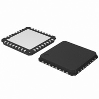
AMIS30623C623BRG ON Semiconductor, AMIS30623C623BRG Datasheet - Page 33

AMIS30623C623BRG
Manufacturer Part Number
AMIS30623C623BRG
Description
IC MOTOR DRIVER/CTLR 32-QFP
Manufacturer
ON Semiconductor
Datasheet
1.AMIS30623C6239RG.pdf
(61 pages)
Specifications of AMIS30623C623BRG
Applications
Stepper Motor Driver
Number Of Outputs
1
Current - Output
800mA
Voltage - Supply
6.5 V ~ 29 V
Operating Temperature
-40°C ~ 165°C
Mounting Type
Surface Mount
Package / Case
32-VSQFP
Mounting Style
SMD/SMT
Lead Free Status / RoHS Status
Lead free / RoHS Compliant
Voltage - Load
-
Lead Free Status / Rohs Status
Lead free / RoHS Compliant
Available stocks
Company
Part Number
Manufacturer
Quantity
Price
Company:
Part Number:
AMIS30623C623BRG
Manufacturer:
ON Semiconductor
Quantity:
1 850
Company:
Part Number:
AMIS30623C623BRG
Manufacturer:
ON Semiconductor
Quantity:
10 000
a problem or not and decide which application strategy to adopt.
Important: While in shutdown mode, since there is no hold
current in the coils, the mechanical load can cause a step loss,
which indeed cannot be flagged by the AMIS−30623.
the circuit enters the sleep mode immediately.
Note: The Priority Encoder is describing the management of
states and commands.
Warning: The application should limit the number of
consecutive GetStatus or GetFullStatus commands to try to
get the AMIS−30623 out of shutdown mode when this
proves to be unsuccessful, e.g. there is a permanent defect.
The reliability of the circuit could be altered since
Get(Full)Status attempts to disable the protection of the
H−bridges.
Motion Detection
internally in the running motor. When the motor is blocked,
e.g. when it hits the end−stop, the velocity and as a result also
the generated back emf, is disturbed. The AMIS−30623
Table 25. Example of Possible Sequence used to Detect and Determine Cause of Motor Shutdown
This can be illustrated in the following sequence given as an application example. The master can check whether there is
If the LIN communication is lost while in shutdown mode,
Motion detection is based on the back emf generated
− The circuit is driven in motor shutdown
− The application is not aware of this
V ABSTH
Figure 20. Triggering of the Stall Flags in Function of Measured Backemf and the Set Threshold Levels
V
V
max
min
<CPFail> = ‘1’ (>15s)
V
Velocity
Vbemf
AbsStall
BB
<ElDef> = ‘1’ or
≤ UV2 (>15s) or
Tj ≥ Tsd or
mode
↓
Back emf
Motor speed
updated by the LIN Master
− The position set−point is
− Motor shutdown mode
− The application is still
SetPosition
⇒ no motion
http://onsemi.com
unaware
frame
↓
t
t
t
33
DeltaStallLo
DeltaStallHi
Vbemf
senses the back emf, calculates a moving average and
compares the value with two independent threshold levels:
Absolute threshold (AbsThr[3:0]) and Delta threshold
(<DelThr[3:0]>). Instructions for correct use of these
two levels in combination with three additional parameters
(<MinSamples>, <FS2StallEn> and <DC100StEn>)
are available in a dedicated Application Note “Robust
Motion Control with AMIS−3062x Stepper Motor Drivers”.
and the resulting back emf increases above the Delta
threshold (+DTHR), then <DelStallHi> is set. When the
motor is slowing down and the resulting back emf decreases
below the Delta threshold (−DTHR), then <DelStallLo>
is set. When the motor is blocked and the velocity is zero
after the acceleration phase, the back emf is low or zero.
When this value is below the Absolute threshold,
<AbsStall> is set. The <Stall> flag is the OR function
of
<AbsStall>.
If the motor is accelerated by a pulling or propelling force
<DelStallLo>
− The application is aware
V
− Reset <TW> or <TSD> or <UV2> or <StepLoss> or
bemf
− Possible new detection of over temperature or low
voltage or electrical problem ⇒ Circuit sets <TW> or
GetFullStatus or
GetStatus frame
<TSD> or <UV2> or <StepLoss> or <ElDef> or
of a problem
<ElDef> or <CPFail> by the application
↓
<CPFail> again at ‘1’
OR
V
bemf
− Possible confirmation of
<DelStallHi>
GetFullStatus or
GetStatus frame
the problem
+DTHR
−DTHR
↓...
t
t
t
OR


