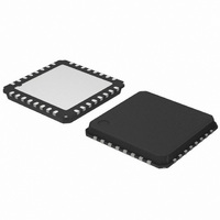
AMIS30623C623BRG ON Semiconductor, AMIS30623C623BRG Datasheet - Page 56

AMIS30623C623BRG
Manufacturer Part Number
AMIS30623C623BRG
Description
IC MOTOR DRIVER/CTLR 32-QFP
Manufacturer
ON Semiconductor
Datasheet
1.AMIS30623C6239RG.pdf
(61 pages)
Specifications of AMIS30623C623BRG
Applications
Stepper Motor Driver
Number Of Outputs
1
Current - Output
800mA
Voltage - Supply
6.5 V ~ 29 V
Operating Temperature
-40°C ~ 165°C
Mounting Type
Surface Mount
Package / Case
32-VSQFP
Mounting Style
SMD/SMT
Lead Free Status / RoHS Status
Lead free / RoHS Compliant
Voltage - Load
-
Lead Free Status / Rohs Status
Lead free / RoHS Compliant
Available stocks
Company
Part Number
Manufacturer
Quantity
Price
Company:
Part Number:
AMIS30623C623BRG
Manufacturer:
ON Semiconductor
Quantity:
1 850
Company:
Part Number:
AMIS30623C623BRG
Manufacturer:
ON Semiconductor
Quantity:
10 000
SetPositionShort
to drive one, two or four motors to a given absolute position.
It applies only for half stepping mode (StepMode[1:0]
= “00”) and is ignored when in other stepping modes. See
Positioning for more details.
SetPositionShort can only be used with a network
implementing a maximum of 16 slave nodes. These 4 bits
SetPositionShort corresponds to the following LIN writing frames:
Where:
Where:
Table 65. SetPositionShort WRITING FRAME TYPE #2
Table 66. SetPositionShort WRITING FRAME TYPE #2
This command is provided to the circuit by the LIN Master
The physical address is coded on 4 bits, hence
(*) According to parity computation
Broad: If broad = ‘0’ all the stepper motors connected to the LIN bus will go to Pos[10:0].
ID[5:0]: Dynamically allocated identifier to two data bytes SetPositionShort command.
(*) according to parity computation
ID[5:0]: Dynamically allocated identifier to four data bytes SetPositionShort command.
Adn[3:0]: Motor #n physical address least significant bits (n ∈ [1,2]).
Posn[10:0]: Signed 11−bit position set point for Motor #n (see RAM Registers)
1. Two (2) data bytes frame for one (1) motor, with specific identifier (type #2)
2. Four (4) data bytes frame for two (2) motors, with specific identifier (type # 2)
Byte
Byte
0
1
2
3
0
1
2
3
4
5
Checksum
Checksum
Content
Identifier
Content
Identifier
Data 1
Data 2
Data 1
Data 2
Data 3
Data 4
Bit 7
Bit 7
*
*
Pos1[10:8]
Pos2[10:8]
Pos[10:8]
Bit 6
Bit 6
*
*
http://onsemi.com
Bit 5
Bit 5
0
1
56
are corresponding to the bits PA[3:0] in OTP memory
(address 0x02) See Physical Address of the Circuit. For
SetPositionShort it is recommended to set HW0,
HW1 and HW2 to ’1’.
describes the cases where a SetPositionShort
command will be ignored.
Checksum over data
Checksum over data
Broad
The priority encoder table (See Priority Encoder)
Bit 4
Bit 4
ID4
0
1
1
Structure
Structure
Pos1[7:0]
Pos2[7:0]
Pos [7:0]
Bit 3
Bit 3
ID3
ID3
Bit 2
Bit 2
ID2
ID2
AD1[3:0]
AD2[3:0]
AD [3:0]
Bit 1
Bit 1
ID1
ID1
Bit 0
Bit 0
ID0
ID0


