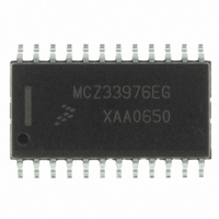
MCZ33976EG Freescale Semiconductor, MCZ33976EG Datasheet - Page 20

MCZ33976EG
Manufacturer Part Number
MCZ33976EG
Description
IC DRIVER DUAL GAUGE SPI 24-SOIC
Manufacturer
Freescale Semiconductor
Type
Serial Peripheral Interface (SPI) Dual Step Motor Gauge Driverr
Datasheet
1.MCZ33976EG.pdf
(41 pages)
Specifications of MCZ33976EG
Applications
Stepper Motor Driver, 2 Phase
Number Of Outputs
2
Current - Output
100mA
Voltage - Supply
6.5 V ~ 26 V
Operating Temperature
-40°C ~ 125°C
Mounting Type
Surface Mount
Package / Case
24-SOIC (7.5mm Width)
Supply Current
4 mA
Maximum Operating Temperature
+ 125 C
Mounting Style
SMD/SMT
Minimum Operating Temperature
- 40 C
Lead Free Status / RoHS Status
Lead free / RoHS Compliant
Voltage - Load
-
Lead Free Status / Rohs Status
Lead free / RoHS Compliant
Available stocks
Company
Part Number
Manufacturer
Quantity
Price
Part Number:
MCZ33976EG
Manufacturer:
FREESCALE
Quantity:
20 000
step for which the Hold Counts are applied:
determined by the value written to HC3:HC0 (HC) and can
range from 0 to 15 steps. This number of hold counts will be
applied to each step below the Hold Count Cut-In as
determined by HCP and RS. The default value of HC is 5.
must be adhered to for the state machine to work properly:
Table 15. Ramp Selection Register (RMPSELR)
The bits in
determines the gauge for which the settings apply (refer to
page 17):
for valid commands.
variable. These bits determine HCP, which is then multiplied
by 8, and added to the RS number, to determine the actual
Hold Count Cut-In Step value. The values of HCP range from
1 to 8 as shown in
.
Table 16. First Hold Count Velocity Position
Hold Counts that will be applied to the steps that are
determined by the HCP2:HCP0 and RS3:RS0 bits. The HC
values range from 0 to 15 and are shown in
default value is 5.
20
33976
FUNCTIONAL DEVICE OPERATION
LOGIC COMMANDS AND REGISTERS
Read
Write GSEL 12 GSEL 11
Bits
The value of RS also determines the last velocity position
Last Velocity Position w/ Hold Counts = RS + 2
The number of hold counts per applicable velocity step is
Note: the following relationship between the variables
GSEL 12 (D12) — Gauge Select bit. The value of this bit
• 1 = Gauge 1
• 0 = Gauge 0
GSEL 11 (D11) — This bit must be transmitted as Logic 0
HCP2 : HPC0 (D10 : D8) — Hold Count Cut-in Point
HC3 : HC0 (D7 : D4) — These bits determine the number of
HCP2
0
0
0
0
1
1
1
1
Table 15
D12
–
HCP1
0
0
1
1
0
0
1
1
are write-only.
Table
D11
–
16. The default value is 2.
HCP0
HCP2
D10
0
1
0
1
0
1
0
1
–
HCP1
D9
–
(HCP x 8 + RS)
Velocity Step
Table
64 + RS
16 + RS
24 + RS
32 + RS
40 + RS
48 + RS
56 + RS
8 + RS
HCP0
D8
–
17. The
HC3
D7
Address 101
–
HC2
D6
the largest value of Hold Counts you can choose is 4.
of the RMPSELR bits are applied to. A GSEL bit set to logic
1 will apply the RMPSELR data to Gauge 1 and, Logic 0 to
Gauge 0, respectively. Configuring both gauges requires two
writes to this register.
Table 17. Hold Counts Per Step
velocity steps that are truncated from the Velocity Position
ramp. The values range from 0 to 15 and are shown in
Table
–
HC x (HCP x 8 - 1) + (225 - RS) < 512
Therefore, if RS = 0 and the Hold Count Cut-In point is 64,
4 * (64 - 1) + (225 - 0) = 477
The GSEL bit determines which of the two gauges the rest
RS3 : RS0 (D3 : D0) — These bits determine the number of
HC3
0
0
0
0
0
0
0
0
1
1
1
1
1
1
1
1
18. The default value is 0.
HC1
D5
–
HC2
0
0
0
0
1
1
1
1
0
0
0
0
1
1
1
1
HC0
D4
–
Analog Integrated Circuit Device Data
HC1
0
0
1
1
0
0
1
1
0
0
1
1
0
0
1
1
RS3
D3
–
HC0
0
1
0
1
0
1
0
1
0
1
0
1
0
1
0
1
Freescale Semiconductor
RS2
D2
–
Hold Counts /
RS1
D1
Step (HC)
–
10
11
12
13
14
15
0
1
2
3
4
5
6
7
8
9
RS0
D0
–


