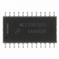
MCZ33976EG Freescale Semiconductor, MCZ33976EG Datasheet - Page 32

MCZ33976EG
Manufacturer Part Number
MCZ33976EG
Description
IC DRIVER DUAL GAUGE SPI 24-SOIC
Manufacturer
Freescale Semiconductor
Type
Serial Peripheral Interface (SPI) Dual Step Motor Gauge Driverr
Datasheet
1.MCZ33976EG.pdf
(41 pages)
Specifications of MCZ33976EG
Applications
Stepper Motor Driver, 2 Phase
Number Of Outputs
2
Current - Output
100mA
Voltage - Supply
6.5 V ~ 26 V
Operating Temperature
-40°C ~ 125°C
Mounting Type
Surface Mount
Package / Case
24-SOIC (7.5mm Width)
Supply Current
4 mA
Maximum Operating Temperature
+ 125 C
Mounting Style
SMD/SMT
Minimum Operating Temperature
- 40 C
Lead Free Status / RoHS Status
Lead free / RoHS Compliant
Voltage - Load
-
Lead Free Status / Rohs Status
Lead free / RoHS Compliant
Available stocks
Company
Part Number
Manufacturer
Quantity
Price
Part Number:
MCZ33976EG
Manufacturer:
FREESCALE
Quantity:
20 000
microcontroller via the status message that the RTZ was
successful. The RTZ automatically disables, allowing other
commands to be valid. In the event the master determines an
RTZ sequence is not working properly (i.e., the RTZ taking
too long), it can disable the command via the RTZR bit RZ1.
accumulator with a predetermined value that will assure an
accurate pointer stall detection. This preloaded value is
determined during application development by disabling the
automatic shutdown feature of the device with the RTZR bit
RZ4. This operating mode allows the master to monitor the
RTZ event, using the accumulator information available via
the SO if the device is configured to provide the RTZ
step, waits for a predetermined blanking time, then
processes the signal for the duration of the full step. When
the pointer reaches the stop and no longer moves, the
dissipating flux is detected. The processed results are placed
in the RTZ accumulator, then compared to a decision
threshold. If the signal exceeds the decision threshold, the
pointer is assumed to be moving. If the threshold value is not
exceeded, the drive sequence is stopped if RTZR bit RZ4 is
logic [0]. If bit RZ4 is logic [1], the RTZ movement will
continue indefinitely until the RTZR bit RZ1 is used to stop the
RTZ event.
magnetic alignment prior to the RTZ event may cause a false
RTZ detection. More specifically, an RTZ event beginning
from a non-full step position may result in an abbreviated
integration value potentially interpreted as a stalled pointer.
Advancing the pointer by at least 12 microsteps clockwise (if
32
33976
FUNCTIONAL DEVICE OPERATION
LOGIC COMMANDS AND REGISTERS
RTZCR bits RC10:RC5 are written to preload the
The IC automatically prepares the non-driven coil at each
A pointer that is not on a full step location or that is in
I
I
COIL
COIL
I
I
I
MAX
I
MAX
MAX
MAX
0
0
0
0
Figure 12. Full Steps Counterclockwise
1
1
Accumulator Status. The unconditional RTZ event can be
turned OFF using the RTZR bit RZ1.
then during an RTZ event the pointer is returned counter-
clockwise (CCW) using full steps at a constant speed
determined by the RTZCR RC3:RC0 and RC12:RC11 bits
during RTZ configuration (see
during an RTZ so that only one coil of the motor is being
driven at any time. The coil not being driven is used to
determine if the pointer is moving. If the pointer is moving, the
EMF signal that is present in the non-driven coil is processed
by integrating the signal present on the opened pin of the coil
while essentially grounding the other end.
PE7 = 0) to the nearest full step position (e.g., 0, 6, 12, 18,
24, etc.) prior to initiating an RTZ ensures the magnetic fields
line up and increases the chances of a successful pointer
stall detection. It is important that the pointer be in a static, or
commanded, position before starting the RTZ event.
Because the time duration and the number of steps the
pointer moves prior to reaching the commanded position can
vary depending upon its status at the time a position change
is communicated, the master should assure sufficient
elapsed time prior to starting an RTZ. If an RTZ is desired
after first enabling the outputs or after forcing a reset of the
device, the pointer should first be commanded to move
12 microsteps clockwise to the nearest full step location.
Because the pointer was in a static position at default, the
master could determine the number of microsteps the device
has taken by monitoring and counting the MOV0. MOV1
device status bit transitions to confirm the pointer is again in
a static position. Alternatively, the user could monitor the
device status bits CMD1 and CMD2.
If the Position 0 location bit is in the default logic [0] mode,
COSINE
2
2
SINE
Analog Integrated Circuit Device Data
3
3
Figure
Freescale Semiconductor
12). Full steps are used
0
0


