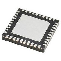
IR3523MTRPBF International Rectifier, IR3523MTRPBF Datasheet - Page 25

IR3523MTRPBF
Manufacturer Part Number
IR3523MTRPBF
Description
IC XPHASE3 CTLR VR11.1 40-MLPQ
Manufacturer
International Rectifier
Series
XPhase3™r
Datasheet
1.IR3523MTRPBF.pdf
(37 pages)
Specifications of IR3523MTRPBF
Applications
Processor
Current - Supply
10mA
Voltage - Supply
4.75 V ~ 7.5 V
Operating Temperature
0°C ~ 100°C
Mounting Type
Surface Mount
Package / Case
40-MLPQ
Ic Function
Dual Output Control IC
Supply Voltage Range
4.75V To 7.5V
Operating Temperature Range
0°C To +150°C
Digital Ic Case Style
MLPQ
No. Of Pins
40
Controller Type
XPhase
Rohs Compliant
Yes
Package
40-Lead MLPQ
Circuit
X-Phase Control IC
Switch Freq (khz)
250kHz to 1.5MHz
Pbf
PbF Option Available
Lead Free Status / RoHS Status
Lead free / RoHS Compliant
DESIGN PROCEDURES - IR3523 AND IR3505 CHIPSET
IR3523 EXTERNAL COMPONENTS
All the output components are selected using one output but suitable for both unless otherwise specified.
Oscillator Resistor Rosc
The IR3523 generates square-wave pulses to synchronize the phase ICs. The switching frequency of the each
phase converter equals the PHSOUT frequency, which is set by the external resistor R
determine the R
number.
Soft Start Capacitor C
The Soft Start capacitor C
PGx delay time and over-current fault latch delay time after PGx.
SS/DELx pin voltage controls the slew rate of the converter output voltage, as shown in Figure 10. Once the
ENABLE pin rises above 1.65V, there is a soft-start delay time TD1 during which SS/DEL pin is charged from
zero to 1.4V. Once SS/DEL reaches 1.4V, the error amplifier output is released to allow the soft start. The soft
start time, TD2, represents the time during which converter voltage rises from zero to VID2 or VOUT1’s boot
voltage (1.1V). The SS/DELx pins voltage rises from 1.4V to VID2 (or VOUT1 boot) plus 1.4V. Power good delay
time, TD3, is the time period from between where VR reaches the VID voltage and PGx signal assertion.
Calculate C
The soft start delay time TD1 and VR ready delay time TD3 are determined by equation (2) and (3) respectively.
Once C
Due to the exponential turn-on slope of the discharge current (47uA), a correction factor (X2.5) is added to the
equation (4) to accurately predict over-current delay time.
SS/DEL
Page 25 of 37
SS/DEL
is chosen, use equation (4) to calculate the maximum over-current fault latch delay time
ROSC
TD
TD
C
based on the required soft start time TD2.
SS
1
3
/
DEL
=
=
value. The CLKOUT frequency equals the switching frequency multiplied by the phase
SS/DEL
C
t
C
OCDEL
=
SS
SS
SS/DEL
TD
/
I
/
DEL
DEL
CHG
2
=
VID
1 *
( *
*
2
programs four different time parameters, soft start delay time, soft start time,
I
5 .
4 .
. 3
CHG
I
∗
93
CHG
=
C
−
=
C
SS
VID
50
SS
TD
I
/
DEL
DISCHG
/
DEL
*
2
10
−
*
*
VID
1 *
. 1
. 0
50
−
6
) 4
12
4 .
*
10
=
=
C
2
−
6
5 .
SS
/
∗
DEL
C
SS
( *
47
50
/
DEL
. 3
*
*
93
10
10
*
−
−
. 0
−
6
VID
6
12
−
(1)
(2)
. 1
) 4
ROSC
June 20, 2008
, use Figure 2 to
(3)
IR3523
t
OCDEL.
(4)


