TMP05AKSZ-500RL7 Analog Devices Inc, TMP05AKSZ-500RL7 Datasheet - Page 17
TMP05AKSZ-500RL7
Manufacturer Part Number
TMP05AKSZ-500RL7
Description
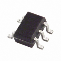
IC PWM TEMP SNSR CMOS/TTL SC70-5
Manufacturer
Analog Devices Inc
Datasheet
1.TMP05ARTZ-500RL7.pdf
(28 pages)
Specifications of TMP05AKSZ-500RL7
Function
Temp Monitoring System (Sensor)
Topology
ADC (Sigma Delta), Averaging Control
Sensor Type
Internal
Sensing Temperature
-40°C ~ 150°C
Output Type
CMOS/TTL
Output Alarm
No
Output Fan
No
Voltage - Supply
3 V ~ 5.5 V
Operating Temperature
-40°C ~ 150°C
Mounting Type
Surface Mount
Package / Case
SC-70-5, SC-88A, SOT-323-5, SOT-353, 5-TSSOP
Ic Output Type
Digital
Sensing Accuracy Range
± 2°C
Supply Current
425µA
Supply Voltage Range
3V To 5.5V
Resolution (bits)
12bit
Sensor Case Style
SC-70
No. Of Pins
5
Temperature Sensor Function
Temp Sensor
Package Type
SC-70
Operating Temperature (min)
-40C
Operating Temperature (max)
150C
Operating Temperature Classification
Automotive
Operating Supply Voltage (min)
3V
Operating Supply Voltage (typ)
3.3/5V
Operating Supply Voltage (max)
5.5V
Accuracy
± 0.5
Rohs Compliant
Yes
Lead Free Status / RoHS Status
Lead free / RoHS Compliant
Lead Free Status / RoHS Status
Lead free / RoHS Compliant, Lead free / RoHS Compliant
Other names
TMP05AKSZ-500RL7TR
Available stocks
Company
Part Number
Manufacturer
Quantity
Price
Company:

Part Number:
TMP05AKSZ-500RL7
Manufacturer:
Analog Devices Inc
Quantity:
1 930


APPLICATION HINTS
THERMAL RESPONSE TIME
The time required for a temperature sensor to settle to a
specified accuracy is a function of the sensor’s thermal mass
and the thermal conductivity between the sensor and the object
being sensed. Thermal mass is often considered equivalent to
capacitance. Thermal conductivity is commonly specified using
the symbol Q and can be thought of as thermal resistance. It is
usually specified in units of degrees per watt of power transferred
across the thermal joint. Thus, the time required for the TMP05/
TMP06 to settle to the desired accuracy is dependent on the
package selected, the thermal contact established in that
particular application, and the equivalent power of the heat
source. In most applications, the settling time is probably best
determined empirically.
SELF-HEATING EFFECTS
The temperature measurement accuracy of the TMP05/TMP06
can be degraded in some applications due to self-heating. Errors
are introduced from the quiescent dissipation and power dissipated
when converting, that is, during T
temperature errors depends on the thermal conductivity of the
TMP05/TMP06 package, the mounting technique, and the
effects of airflow. Static dissipation in the TMP05/TMP06 is
typically 10 μW operating at 3.3 V with no load. In the 5-lead
SC-70 package mounted in free air, this accounts for a
temperature increase due to self-heating of
In addition, power is dissipated by the digital output, which is
capable of sinking 800 μA continuously (TMP05). Under an
800 μA load, the output can dissipate
For example, with T
dissipation due to the digital output is approximately 0.21 mW.
In a free-standing SC-70 package, this accounts for a tempera-
ture increase due to self-heating of
This temperature increase directly adds to that from the
quiescent dissipation and affects the accuracy of the TMP05/
TMP06 relative to the true ambient temperature.
It is recommended that current dissipated through the device be
kept to a minimum because it has a proportional effect on the
temperature error.
ΔT = P
P
ΔT = P
DISS
= (0.4 V)(0.8 mA)((T
DISS
DISS
× θ
× θ
JA
JA
L
= 10 μW × 534.7°C/W = 0.0053°C
= 0.21 mW × 534.7°C/W = 0.112°C
= 80 ms and T
L
)/T
L
. The magnitude of these
H
H
+ T
= 40 ms, the power
L
))
Rev. B | Page 17 of 28
(5)
(6)
(7)
SUPPLY DECOUPLING
The TMP05/TMP06 should be decoupled with a 0.1 μF ceramic
capacitor between V
if the TMP05/TMP06 are mounted remotely from the power
supply. Precision analog products such as the TMP05/TMP06
require a well filtered power source. Because the parts operate
from a single supply, simply tapping into the digital logic power
supply could appear to be a convenient option. Unfortunately,
the logic supply is often a switch-mode design, which generates
noise in the 20 kHz to 1 MHz range. In addition, fast logic gates
can generate glitches hundreds of mV in amplitude due to
wiring resistance and inductance.
If possible, the TMP05/TMP06 should be powered directly
from the system power supply. This arrangement, shown in
Figure 30, isolates the analog section from the logic switching
transients. Even if a separate power supply trace is not available,
generous supply bypassing reduces supply-line-induced errors.
Local supply bypassing consisting of a 0.1 μF ceramic capacitor
is critical for the temperature accuracy specifications to be
achieved. This decoupling capacitor must be placed as close as
possible to the TMP05/TMP06 V
decoupling capacitor is Phicomp’s 100 nF, 50 V X74.
It is important to keep the capacitor package size as small as
possible because ESL (equivalent series inductance) increases
with increasing package size. Reducing the capacitive value
below 100 nF increases the ESR (equivalent series resistance).
Using a capacitor with an ESL of 1 nH and an ESR of 80 mΩ is
recommended.
TTL/CMOS
CIRCUITS
LOGIC
Figure 30. Use Separate Traces to Reduce Power Supply Noise
POWER
SUPPLY
DD
and GND. This is particularly important
DD
pin. A recommended
TMP05/TMP06
0.1µF
TMP05/
TMP06
Related parts for TMP05AKSZ-500RL7
Image
Part Number
Description
Manufacturer
Datasheet
Request
R

Part Number:
Description:
IC,TEMPERATURE SENSOR,HYBRID,TSSOP,5PIN,PLASTIC
Manufacturer:
Analog Devices Inc
Datasheet:
Part Number:
Description:
IC,TEMPERATURE SENSOR,HYBRID,TSSOP,5PIN,PLASTIC
Manufacturer:
Analog Devices Inc
Datasheet:

Part Number:
Description:
±1.7g Dual-Axis IMEMS Accelerometer Evaluation Board
Manufacturer:
Analog Devices Inc
Datasheet:

Part Number:
Description:
Inertial Sensor Evaluation System
Manufacturer:
Analog Devices Inc
Datasheet:
Part Number:
Description:
Manufacturer:
Analog Devices Inc
Datasheet:
Part Number:
Description:
Manufacturer:
Analog Devices Inc
Datasheet:
Part Number:
Description:
Manufacturer:
Analog Devices Inc
Datasheet:
Part Number:
Description:
Manufacturer:
Analog Devices Inc
Datasheet:
Part Number:
Description:
Manufacturer:
Analog Devices Inc
Datasheet:
Part Number:
Description:
Manufacturer:
Analog Devices Inc
Datasheet:
Part Number:
Description:
Manufacturer:
Analog Devices Inc
Datasheet:
Part Number:
Description:
Manufacturer:
Analog Devices Inc
Datasheet:
Part Number:
Description:
Manufacturer:
Analog Devices Inc
Datasheet: