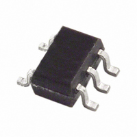
TMP05AKSZ-500RL7 Analog Devices Inc, TMP05AKSZ-500RL7 Datasheet - Page 18

TMP05AKSZ-500RL7
Manufacturer Part Number
TMP05AKSZ-500RL7
Description
IC PWM TEMP SNSR CMOS/TTL SC70-5
Manufacturer
Analog Devices Inc
Datasheet
1.TMP05ARTZ-500RL7.pdf
(28 pages)
Specifications of TMP05AKSZ-500RL7
Function
Temp Monitoring System (Sensor)
Topology
ADC (Sigma Delta), Averaging Control
Sensor Type
Internal
Sensing Temperature
-40°C ~ 150°C
Output Type
CMOS/TTL
Output Alarm
No
Output Fan
No
Voltage - Supply
3 V ~ 5.5 V
Operating Temperature
-40°C ~ 150°C
Mounting Type
Surface Mount
Package / Case
SC-70-5, SC-88A, SOT-323-5, SOT-353, 5-TSSOP
Ic Output Type
Digital
Sensing Accuracy Range
± 2°C
Supply Current
425µA
Supply Voltage Range
3V To 5.5V
Resolution (bits)
12bit
Sensor Case Style
SC-70
No. Of Pins
5
Temperature Sensor Function
Temp Sensor
Package Type
SC-70
Operating Temperature (min)
-40C
Operating Temperature (max)
150C
Operating Temperature Classification
Automotive
Operating Supply Voltage (min)
3V
Operating Supply Voltage (typ)
3.3/5V
Operating Supply Voltage (max)
5.5V
Accuracy
± 0.5
Rohs Compliant
Yes
Lead Free Status / RoHS Status
Lead free / RoHS Compliant
Lead Free Status / RoHS Status
Lead free / RoHS Compliant, Lead free / RoHS Compliant
Other names
TMP05AKSZ-500RL7TR
Available stocks
Company
Part Number
Manufacturer
Quantity
Price
Company:
Part Number:
TMP05AKSZ-500RL7
Manufacturer:
Analog Devices Inc
Quantity:
1 930
TMP05/TMP06
LAYOUT CONSIDERATIONS
Digital boards can be electrically noisy environments and
glitches are common on many of the signals in the system.
The likelihood of glitches causing problems to the TMP05/
TMP06 OUT pin is very minute. The typical impedance of the
TMP05/TMP06 OUT pin when driving low is 55 Ω. When
driving high, the TMP05 OUT pin is similar. This low imped-
ance makes it very difficult for a glitch to break the V
thresholds. There is a slight risk that a sizeable glitch could
cause problems. A glitch can only cause problems when the
OUT pin is low during a temperature measurement. If a glitch
occurs that is large enough to fool the master into believing that
the temperature measurement is over, the temperature read
would not be the actual temperature. In most cases, the master
spots a temperature value that is erroneous and can request
another temperature measurement for confirmation. One area
that can cause problems is if this very large glitch occurs near
the end of the low period of the mark-space waveform, and the
temperature read back is so close to the expectant temperature
that the master does not question it.
One layout method that helps in reducing the possibility of a
glitch is to run ground tracks on either side of the OUT line.
Use a wide OUT track to minimize inductance and reduce noise
pickup. A 10 mil track minimum width and spacing is
recommended. Figure 31 shows how glitch protection traces
could be laid out.
Another method that helps reduce the possibility of a glitch is to
use a 50 ns glitch filter on the OUT line. The glitch filter
eliminates any possibility of a glitch getting through to the
master or being passed along a daisy chain.
TEMPERATURE MONITORING
The TMP05/TMP06 are ideal for monitoring the thermal
environment within electronic equipment. For example, the
surface-mounted package accurately reflects the exact thermal
conditions that affect nearby integrated circuits.
The TMP05/TMP06 measure and convert the temperature at
the surface of their own semiconductor chip. When the
TMP05/TMP06 are used to measure the temperature of a
GND
GND
Figure 31. Use Separate Traces to Reduce Power Supply Noise
OUT
10 MIL
10 MIL
10 MIL
10 MIL
10 MIL
IL
and V
Rev. B | Page 18 of 28
IH
nearby heat source, the thermal impedance between the heat
source and the TMP05/TMP06 must be considered. Often, a
thermocouple or other temperature sensor is used to measure
the temperature of the source, while the TMP05/TMP06
temperature is monitored by measuring T
thermal impedance is determined, the temperature of the heat
source can be inferred from the TMP05/TMP06 output.
One example of using the TMP05/TMP06’s unique properties is
in monitoring a high power dissipation microprocessor. Each
TMP05/TMP06 part, in a surface-mounted package, is
mounted directly beneath the microprocessor’s pin grid array
(PGA) package. In a typical application, the TMP05/TMP06
output is connected to an ASIC, where the pulse width is
measured. The TMP05/TMP06 pulse output provides a
significant advantage in this application because it produces a
linear temperature output while needing only one I/O pin and
without requiring an ADC.
DAISY-CHAIN APPLICATION
This section provides an example of how to connect two
TMP05s in daisy-chain mode to a standard 8052 microcon-
troller core. The
core processing engine is the 8052. Figure 31 shows how to
interface to the 8052 core device. The TMP05 Program Code
Example 1 section shows how to communicate from the
ADuC812
used with the
8052 core.
Figure 32 is a diagram of the input waveform into the
from the TMP05 daisy chain. It illustrates how the code’s variables
are assigned and it should be referenced when reading the
TMP05 Program Code Example 1. Application notes showing
the TMP05 working with other types of microcontrollers are
available from Analog Devices at www.analog.com.
Figure 33 shows how the three devices are hardwired together.
Figure 34 to Figure 36 are flow charts for this program.
TIMER T0
STARTS
TEMP_HIGH0
Figure 32. Reference Diagram for Software Variables
to two daisy-chained TMP05s. This code can also be
TEMPSEGMENT = 1 TEMPSEGMENT = 2 TEMPSEGMENT = 3
INTO
ADuC831
in the TMP05 Program Code Example 1
ADuC812
or any microprocessor running on an
TEMP_LOW0
is the microcontroller used and the
TEMP_HIGH1
INTO
H
TEMP_HIGH2
and T
TEMP_LOW1
INTO
L
. Once the
ADuC812


