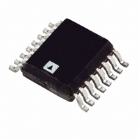
ADT7517ARQZ Analog Devices Inc, ADT7517ARQZ Datasheet - Page 24

ADT7517ARQZ
Manufacturer Part Number
ADT7517ARQZ
Description
IC SENSOR TEMP QD ADC/DAC 16QSOP
Manufacturer
Analog Devices Inc
Datasheet
1.ADT7517ARQZ.pdf
(44 pages)
Specifications of ADT7517ARQZ
Function
Temp Monitoring System (Sensor)
Topology
ADC, Comparator, Multiplexer, Register Bank
Sensor Type
External & Internal
Sensing Temperature
-40°C ~ 120°C, External Sensor
Output Type
I²C™, MICROWIRE™, QSPI™, SPI™
Output Alarm
No
Output Fan
No
Voltage - Supply
2.7 V ~ 5.5 V
Operating Temperature
-40°C ~ 120°C
Mounting Type
Surface Mount
Package / Case
16-QSOP
Ic Output Type
Voltage
Sensing Accuracy Range
± 0.5°C
Supply Current
2.2mA
Supply Voltage Range
2.7V To 5.5V
Resolution (bits)
10bit
Sensor Case Style
QSOP
No. Of Pins
16
Temperature Sensor Function
Temp Sensor
Resolution
10b
Operating Temperature (min)
-40C
Operating Temperature (max)
120C
Operating Supply Voltage (min)
2.7V
Operating Supply Voltage (typ)
3.3/5V
Operating Supply Voltage (max)
5.5V
Lead Free Status / RoHS Status
Lead free / RoHS Compliant
Lead Free Status / RoHS Status
Lead free / RoHS Compliant, Lead free / RoHS Compliant
Available stocks
Company
Part Number
Manufacturer
Quantity
Price
Company:
Part Number:
ADT7517ARQZ
Manufacturer:
Analog Devices Inc
Quantity:
135
ADT7516/ADT7517/ADT7519
AIN Interrupts
The measured results from the AIN inputs are compared with
the AIN V
equal to comparison) limits. An interrupt occurs if the AIN
inputs exceed or equal the limit registers. These voltage limits
are stored in on-chip registers. Note that the limit registers are
8 bits long and the AIN conversion result is 10 bits long. If the
HIGH
Figure 52. Equivalent Analog Input ESD Circuit
(greater than comparison) and V
AIN
4pF
COMPARISONS
READ RESET
WATCHDOG
S/W RESET
LIMIT
100Ω
AIN1 TO AIN4)
REGISTER 2
INTERRUPT
INTERRUPT
(TEMP AND
REGISTER
STATUS
STATUS
(V
Figure 53. ADT7516/ADT7517/ADT7519 Interrupt Structure
DD
)
LOW
(less than or
CONFIGURATION
REGISTER 1
REGISTERS
INTERRUPT
Rev. B | Page 24 of 44
CONTROL
MASK
INTERNAL
TEMP
EXTERNAL
TEMP
V
DIODE
FAULT
AIN1 TO AIN4
voltage limits are not masked out, then any out-of-limit compari-
sons generate flags that are stored in the Interrupt Status 1
register (Address = 0x00) and one or more out-of-limit results
cause the INT/ INT output to pull either high or low depending
on the output polarity setting. It is good design practice to mask
out interrupts for channels that are of no concern to the
application. Figure 53 shows the interrupt structure for the
ADT7516/ ADT7517/ADT7519. It gives a block diagram
representation of how the various measurement channels affect
the INT/ INT pin.
DD
ENABLE BIT
INT/INT
INT/INT
(LATCHED OUTPUT)


