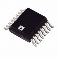
ADT7518ARQ-REEL Analog Devices Inc, ADT7518ARQ-REEL Datasheet - Page 10

ADT7518ARQ-REEL
Manufacturer Part Number
ADT7518ARQ-REEL
Description
IC SENSOR TEMP W/ADC/DAC 16QSOP
Manufacturer
Analog Devices Inc
Datasheet
1.ADT7518ARQ.pdf
(40 pages)
Specifications of ADT7518ARQ-REEL
Rohs Status
RoHS non-compliant
Function
Temp Monitoring System (Sensor)
Topology
ADC, Comparator, Multiplexer, Register Bank
Sensor Type
External & Internal
Sensing Temperature
-40°C ~ 120°C, External Sensor
Output Type
I²C™, MICROWIRE™, QSPI™, SPI™
Output Alarm
No
Output Fan
No
Voltage - Supply
2.7 V ~ 5.5 V
Operating Temperature
-40°C ~ 120°C
Mounting Type
Surface Mount
Package / Case
16-QSOP
ADT7518
TERMINOLOGY
Relative Accuracy
Relative accuracy or integral nonlinearity (INL) is a measure of
the maximum deviation, in LSBs, from a straight line passing
through the endpoints of the transfer function. Typical INL
versus code plots can be seen in Figure 10, Figure 11, and
Figure 12.
Differential Nonlinearity
Differential nonlinearity (DNL) is the difference between the
measured change and the ideal 1 LSB change between any two
adjacent codes. A specified differential nonlinearity of ±0.9 LSB
maximum ensures monotonicity. Typical DAC DNL versus code
plots can be seen in Figure 13, Figure 14, and Figure 15.
Total Unadjusted Error (TUE)
Total unadjusted error is a comprehensive specification that
includes the sum of the relative accuracy error, gain error, and
offset error under a specified set of conditions.
Offset Error
This is a measure of the offset error of the DAC and the output
amplifier (see Figure 8 and Figure 9). It can be negative or
positive, and it is expressed in mV.
Offset Error Match
This is the difference in offset error between any two channels.
Gain Error
This is a measure of the span error of the DAC. It is the
deviation in slope of the actual DAC transfer characteristic
from the ideal expressed as a percentage of the full-scale range.
Gain Error Match
This is the difference in gain error between any two channels.
Offset Error Drift
This is a measure of the change in offset error with changes in
temperature. It is expressed in (ppm of full-scale range)/°C.
Gain Error Drift
This is a measure of the change in gain error with changes in
temperature. It is expressed in (ppm of full-scale range)/°C.
Long Term Temperature Drift
This is a measure of the change in temperature error over time.
It is expressed in °C. The concept of long-term stability has been
used for many years to describe the amount an IC’s parameter
shifts during its lifetime. This is a concept that has typically
been applied to both voltage references and monolithic temp-
erature sensors. Unfortunately, integrated circuits cannot be
evaluated at room temperature (25°C) for 10 years or so to
determine this shift. Manufacturers perform accelerated lifetime
testing of integrated circuits by operating ICs at elevated temp-
eratures (between 125°C and 150°C) over a shorter period
(typically between 500 and 1,000 hours). As a result, the lifetime
of an integrated circuit is significantly accelerated due to the
Rev. A | Page 10 of 40
increase in rates of reaction within the semiconductor material.
DC Power Supply Rejection Ratio (PSRR)
This indicates how the output of the DAC is affected by changes
in the supply voltage. PSRR is the ratio of the change in V
a change in V
in dB. V
DC Crosstalk
This is the dc change in the output level of one DAC in response
to a change in the output of another DAC. It is measured with a
full-scale output change on one DAC while monitoring another
DAC. It is expressed in µV.
Reference Feedthrough
This is the ratio of the amplitude of the signal at the DAC out-
put to the reference input when the DAC output is not being
updated (i.e., LDAC is high). It is expressed in dB.
Channel-to-Channel Isolation
This is the ratio of the amplitude of the signal at the output of
one DAC to a sine wave on the reference input of another DAC.
It is measured in dB.
Major-Code Transition Glitch Energy
Major-code transition glitch energy is the energy of the impulse
injected into the analog output when the code in the DAC
register changes state. It is normally specified as the area of the
glitch in nV-s and is measured when the digital code is changed
by 1 LSB at the major carry transition (011...1 to 100...00 or
100...00 to 011...11).
Digital Feedthrough
Digital feedthrough is a measure of the impulse injected into
the analog output of a DAC from the digital input pins of the
device but is measured when the DAC is not being written to. It
is specified in nV-s and is measured with a full-scale change on
the digital input pins, i.e., from all 0s to all 1s or vice versa.
Digital Crosstalk
This is the glitch impulse transferred to the output of one DAC
at midscale in response to a full-scale code change (all 0s to all
1s and vice versa) in the input register of another DAC. It is
measured in standalone mode and is expressed in nV-s.
Analog Crosstalk
This is the glitch impulse transferred to the output of one DAC
due to a change in the output of another DAC. It is measured by
loading one of the input registers with a full-scale code change
(all 0s to all 1s and vice versa) while keeping LDAC high. Then
pulse LDAC low and monitor the output of the DAC whose
digital code was not changed. The area of the glitch is expressed
in nV-s.
REF
is held at 2 V and V
DD
for full-scale output of the DAC. It is measured
DD
is varied ±10%.
OUT
to


