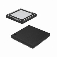
ISL6265HRTZ-T Intersil, ISL6265HRTZ-T Datasheet - Page 18

ISL6265HRTZ-T
Manufacturer Part Number
ISL6265HRTZ-T
Description
IC CTLR MULTI-OUTPUT 48-TQFN
Manufacturer
Intersil
Datasheet
1.ISL6265HRTZ.pdf
(24 pages)
Specifications of ISL6265HRTZ-T
Applications
Controller, AMD SVI Capable Mobile
Voltage - Input
5 ~ 24 V
Number Of Outputs
3
Voltage - Output
0.5 ~ 1.55 V
Operating Temperature
-10°C ~ 100°C
Mounting Type
Surface Mount
Package / Case
48-TQFN
Lead Free Status / RoHS Status
Lead free / RoHS Compliant
unnecessary conduction losses. In DE, the ISL6265 Core
regulators automatically enter DCM after the PHASE pin has
detected positive voltage and LGATE was allowed to go
high. The NB regulator enters DCM after the PHASE pin has
detected positive voltage and LGATE was allowed to go high
for eight consecutive PWM switching cycles. The ISL6265
turns off the low-side MOSFET once the phase voltage turns
positive, indicating negative inductor current. The ISL6265
returns to CCM on the following cycle after the PHASE pin
detects negative voltage, indicating that the body diode of
the low-side MOSFET is conducting positive inductor
current.
Efficiency can be further improved with a reduction of
unnecessary switching losses by reducing the PWM
frequency. It is characteristic of the R
PWM frequency to decrease while in diode emulation. The
extent of the frequency reduction is proportional to the
reduction of load current. Upon entering DCM, the North
Bridge PWM frequency makes an initial step-reduction
because of a 33% step-increase of the window voltage V
Power-Savings Mode
The ISL6265 has two operating modes to optimize efficiency
based on the state of the PSI_L input from the AMD SVI
control signal. When this input is low, the controller expects
to deliver low power and enters a power-savings mode to
improve efficiency in this low power state. The controller’s
operational modes are designed to work in conjunction with
the AMD SVI control signal to maintain the optimal system
configuration for all conditions.
Northbridge And Dual Plane Core
While PSI_L is high, the controller operates all three
regulators in forced CCM. If PSI_L is asserted low by the
SVI interface, the ISL6265 initiates DE in all three regulators.
This transition allows the controller to achieve the highest
possible efficiency over the entire load range for each
output. A smooth transition is facilitated by the R
technology
synthesized ripple current throughout mode transitions of
each regulator.
Uniplane Core
In uniplane mode, the ISL6265 Core regulator is in 2-phase
multiphase mode. The controller operates with both phases
fully active, responding rapidly to transients and delivering
the maximum power to the load. When the processor asserts
PSI_L low under reduced load levels, the ISL6265 sheds
one phase to eliminate switching losses associated with the
idle channel. Even with the regulator operating in
single-phase mode, transient response capability is
maintained.
While operating in single-phase DE with PSI_L low, the
lower MOSFET driver switches the lower MOSFET off at the
point of zero inductor current to prevent discharge current
™
, which correctly maintains the internally
18
3
architecture for the
3
W
.
ISL6265
from flowing from the output capacitor bank through the
inductor. In DCM, switching frequency is proportionately
reduced, thus greatly reducing both conduction and
switching loss. In DCM, the switching frequency is defined
by Equation 12.
Where F
Equation 3.
Fault Monitoring and Protection
The ISL6265 actively monitors Core and Northbridge output
voltages and currents to detect fault conditions. These fault
monitors trigger protective measures to prevent damage to
the processor. One common power good indicator is
provided for linking to external system monitors.
Power Good Signal
The power-good pin (PGOOD) is an open-drain logic output
that signals if the ISL6265 is not regulating Core and
Northbridge output voltages within the proper levels or
output current in one or more outputs has exceeded the
maximum current setpoint.
This pin must be tied to a +3.3V or +5V source through a
resistor. During shutdown and soft-start, PGOOD is pulled
low and is released high only after a successful soft-start has
raised Core and Northbridge output voltages within
operating limits. PGOOD is pulled low when an overvoltage,
undervoltage, or overcurrent (OC) condition is detected on
any output or when the controller is disabled by a POR or
forcing enable (EN) low. Once a fault condition is triggered,
the controller acts to protect the processor. The controller
latches off and PGOOD is pulled low. Toggling EN or VCC
initiates a soft-start of all outputs. In the event of an OV, the
controller will initiate a soft-start by toggling EN.
Overcurrent Protection
Core and Northbridge outputs feature two different methods
of current sensing. Core output current sensing is achieved
via inductor DCR or discrete resistor sensing. The
Northbridge controller uses lower MOSFET r
to detect output current.
CORE OC DETECTION
Core outputs feature an OC monitor which compares a
voltage set at the OCSET pin to the voltage measured
across the current sense capacitor, V
across the current sense capacitor exceeds the programmed
trip level, the comparator signals an OC fault. Figure 10
shows the basic OC functions within the IC.
F
DCM
=
CCM
F
-------------------
1.33
CCM
is equivalent to the Core frequency set by
2
2
⋅
------------------------------------ -
V
O
2 L I
⋅
⋅
⎛
⎜
⎝
1
–
⋅
---------
V
O
V
IN
O
⎞
⎟
⎠
C
. When the voltage
DS(ON)
May 13, 2009
sensing
(EQ. 12)
FN6599.1


