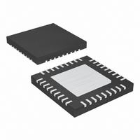
MAX8720ETX+ Maxim Integrated Products, MAX8720ETX+ Datasheet - Page 10

MAX8720ETX+
Manufacturer Part Number
MAX8720ETX+
Description
IC CNTRL VID STP DWN 36-TQFN
Manufacturer
Maxim Integrated Products
Datasheet
1.MAX8720ETXT.pdf
(31 pages)
Specifications of MAX8720ETX+
Applications
Controller, CPU GPU
Voltage - Input
2 ~ 28 V
Number Of Outputs
1
Voltage - Output
0.28 ~ 1.85 V
Operating Temperature
0°C ~ 85°C
Mounting Type
Surface Mount
Package / Case
36-TQFN Exposed Pad
Output Voltage
0.275 V to 1.85 V
Input Voltage
2 V to 28 V
Mounting Style
SMD/SMT
Maximum Operating Temperature
+ 85 C
Minimum Operating Temperature
- 40 C
Lead Free Status / RoHS Status
Lead free / RoHS Compliant
Dynamically Adjustable 6-Bit VID
Step-Down Controller
10
28 QSOP
______________________________________________________________________________________
7, 8
10
11
12
1
2
3
4
5
6
9
PIN
36 THIN
QFN
4, 5
33
34
35
10
1
2
3
7
8
9
NAME
S0, S1
SHDN
TIME
TON
ILIM
FBS
V
REF
CC
V+
FB
CC
Battery Voltage-Sense Connection. Connect V+ to input power source. V+ is used only
for PWM one-shot timing. DH on-time is inversely proportional to input voltage over a 2V
to 28V range.
Shutdown Control Input. Connect SHDN to V
GND to put the controller into its shutdown state. Forcing SHDN to 12V to 15V disables
both the overvoltage-protection and undervoltage-protection circuits and clears the fault
latch. Do not connect SHDN to >15V.
Slew-Rate Adjustment Pin. Connect a resistor from TIME to GND to set the internal slew-
rate clock. A 470kΩ to 22kΩ resistor sets the clock from 38kHz to 818kHz, f
150kHz x 120kΩ / R
during power-up and power-down transient.
Fast Feedback Input. Connect FB to the junction of the external inductor and output-
capacitor node (Figure 1).
Feed b ack Rem ote- S ense Inp ut. For nonvol tag e- p osi ti oned ci r cui ts, connect FBS to V
d i r ectl y at the l oad . FBS i nter nal l y connects to the i nteg r ator that fi ne tunes the D C outp ut
vol tag e. For vol tag e- p osi ti oned ci r cui ts, connect FBS d i r ectl y to FB near the IC to d i sab l e the
FBS r em ote- sense i nteg r ator am p l i fi er . To d i sab l e al l thr ee i nteg r ator am p l i fi er s, connect FBS
to V
Integ r ator C ap aci tor C onnecti on. C onnect a 47p F to 1000p F ( 47p F typ ) cap aci tor fr om C C to
AGN D to set the i nteg r ati on ti m e constant. C C can b e l eft op en i f FBS i s connected to V
S usp end - M od e V ol tag e- S el ect Inp ut. S 0 and S 1 ar e four - l evel d i g i tal i np uts that sel ect the
susp end - m od e V ID cod e for the susp end - m od e m ul ti p l exer i np uts. If S U S i s hi g h, the
susp end - m od e V ID cod e i s d el i ver ed to the D AC .
Anal og S up p l y Inp ut. C onnect to the system sup p l y vol tag e ( + 4.5V to + 5.5V ) thr oug h a ser i es
10Ω r esi stor . Byp ass V
On-Time Selection Control Input. This is a four-level input that sets the K-factor to
determine DH on-time. Connect TON to the following pins for the indicated operation:
2.0V Reference Voltage Output. Bypass REF to analog ground with a 0.22µF or greater
ceramic capacitor. The reference can source up to 50µA for external loads. Loading REF
degrades output voltage accuracy according to the REF load regulation error.
Current-Limit Adjustment. The PGND–LX current-limit threshold defaults to 100mV if ILIM
is connected to V
voltage seen at ILIM over a 0.5V to 3.0V range. The logic threshold for switchover to the
100mV default value is approximately V
threshold.
GND = 1000kHz
REF = 550kHz
Open = 300kHz
V
C C
CC
.
= 200kHz
CC
TIME
. In adjustable mode, the current-limit threshold voltage is 1/10th the
C C
. To reduce inrush current, f
to anal og g r ound w i th a 1µF or g r eater cer am i c cap aci tor .
FUNCTION
CC
- 1V. Connect ILIM to REF for a fixed 200mV
CC
for normal operation. Connect SHDN to
SLEW
= 150kHz x 120kΩ / 4 x R
Pin Description
SLEW
OU T
=
C C
TIME
.


