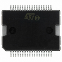
L6701 STMicroelectronics, L6701 Datasheet - Page 32

L6701
Manufacturer Part Number
L6701
Description
IC CTRLR 3PH VR10/9/K8 PWRSO-36
Manufacturer
STMicroelectronics
Datasheet
1.L6701TR.pdf
(44 pages)
Specifications of L6701
Applications
Controller, Intel VR9, VR10, K8
Voltage - Input
12V
Number Of Outputs
3
Voltage - Output
0.8 ~ 1.85 V
Operating Temperature
0°C ~ 70°C
Mounting Type
Surface Mount
Package / Case
36-PowerSOIC
Output Voltage
0.8 V to 1.85 V
Output Current
1.5 A
Switching Frequency
110 KHz
Mounting Style
SMD/SMT
Maximum Operating Temperature
+ 125 C
Minimum Operating Temperature
0 C
Lead Free Status / RoHS Status
Lead free / RoHS Compliant
Available stocks
Company
Part Number
Manufacturer
Quantity
Price
13 Output voltage Monitor and Protections
32/44
inductor current, the ripple entity, when not negligible, impacts on the real OC threshold value
and must be considered.
The device detects an Over Current condition for each phase when the current information
I
relative LS MOSFET on, also skipping clock cycles, until the threshold is crossed back and
I
of each inductor current ripple). After exiting the OC condition, the LS MOSFET is turned off
and the HS is turned on with a duty cycle driven by the PWM comparator.
The device enters in Quasi-Constant-Current operation: the low-side MOSFETs stays ON until
the current read becomes lower than I
side MOSFET can be then turned ON with a T
off and the device works in the usual way until another OCP event is detected.
This means that the average current delivered can slightly increase in Quasi-Constant-Current
operation since the current ripple increases. In fact, the ON time increases due to the OFF time
rise because of the current has to reach the I
the ON time reaches its maximum value (see
works in Real Constant Current and the output voltage decrease as the load increase. Crossing
the UVP threshold causes the device to latch driving high the OSC pin.
It can be observed that the peak current (I
as follow:
Where V
threshold is crossed, all MOSFETs are turned off, the FAULT pin is driven high and the device
stops working. Cycle the power supply or the EN pin to restart operation.
The maximum average current during the Constant-Current behavior results (see
in this particular situation, the switching frequency for each phase results reduced. The ON time
is the maximum allowed T
Figure 15. Constant Current Operation
I
I
ISENx
ISENx
PEAK
OCPx
I
MAX
I
PEAK
T
results being lower than the I
overcomes the fixed threshold of I
ON(max)
outMIN
T
=
SW
I
OCPx
LS ON Skipping
is the UVP threshold, (inductor saturation must be considered). When that
Clock Cycles
T
+
OFF
I
V
------------------------------------------ - T
MAX tot
IN
=
–
ON(max)
,
V
L
OUT m in
L
T
⋅
ON(max)
=
I
------------------------------------ -
PEAK
3 I
(
while the OFF time depends on the application:
OCTH
T
V
⋅
SW
OUT
MAX
–
)
OCPx
⋅
I
OCPx
OCTH
threshold (this implies that the device limits the bottom
ON m ax
PEAK
=
(I
(
OCPx
INFOx
3
. When this happens, the device keeps the
Section
ON
⋅
) is greater than I
⎛
⎝
I
)
imposed by the control loop after the LS turn-
OCPx
bottom. The worst-case condition is when
< I
=
I
OCTH
10.5). When this happens, the device
O CPx
f
=
+
I
------------------------------------ -
--------------------------------------------- -
T
PEAK
) skipping clock cycles. The high
O N max
0.40 V
+
V
V
------------------------------------------ - 0.40 T
(
OUT
IN
IN
2
–
OCPx
(I
DROOP
1
I
–
I
O CPx
)
OCP
V
+
Constant Current (Exploded)
Limted-T
Resulting Out. Char.
UVP Threshold
O UT min
L
T
but it can be determined
= N x I
= N x 35µA)
OFF
⎞
⎠
(
OCPx
ON
)
Char.
⋅
Figure
Droop Effect
⋅
I
MAX,tot
SW
L6701
15):
I
OUT


