LM25011MY/NOPB National Semiconductor, LM25011MY/NOPB Datasheet - Page 12
LM25011MY/NOPB
Manufacturer Part Number
LM25011MY/NOPB
Description
IC BUCK ADJ 2A 10MSOP
Manufacturer
National Semiconductor
Type
Step-Down (Buck)r
Datasheet
1.LM25011MYNOPB.pdf
(20 pages)
Specifications of LM25011MY/NOPB
Internal Switch(s)
Yes
Synchronous Rectifier
No
Number Of Outputs
1
Voltage - Output
2.51 ~ 40 V
Current - Output
2A
Frequency - Switching
Up to 2MHz
Voltage - Input
6 ~ 42 V
Operating Temperature
-40°C ~ 125°C
Mounting Type
Surface Mount
Package / Case
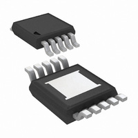
10-MSOP Exposed Pad, 10-HMSOP, 10-eMSOP
Power - Output
155mW
Primary Input Voltage
42V
No. Of Outputs
1
Output Voltage
40V
Output Current
2A
No. Of Pins
10
Operating Temperature Range
-40°C To +125°C
Msl
MSL 3 - 168 Hours
Filter Terminals
SMD
Rohs Compliant
Yes
Lead Free Status / RoHS Status
Lead free / RoHS Compliant
Other names
LM25011MYTR
Available stocks
Company
Part Number
Manufacturer
Quantity
Price
Company:

Part Number:
LM25011MY/NOPB
Manufacturer:
ATMEL
Quantity:
101
Part Number:
LM25011MY/NOPB
Manufacturer:
TI/德州仪器
Quantity:
20 000


www.national.com
Ripple Requirements
The LM25011 requires about 25mVp-p of ripple voltage at the
CS pin. Higher switching frequency may require more ripple.
That ripple voltage is generated by the decreasing recirculat-
ing current (the inductor’s ripple current) through R
the off-time. See Figure 3.
The ripple voltage is equal to:
where ΔI is the inductor current ripple amplitude, and R
the current sense resistor at the CS pin.
More ripple can be achieved by decreasing the inductor value.
The LM25011A, with its shorter minimum off-time, typically
will require more ripple than the LM25011. An external circuit
to increase the effective ripple voltage may be needed. Dif-
ferent methods of generating this ripple are explained in the
“Application Information” section.
FIGURE 3. CS Pin Waveform
V
RIPPLE
= ΔI x R
S
FIGURE 2. Normal and Current Limit Operation
30094625
S
during
S
is
12
N-Channel Buck Switch and Driver
The LM25011 integrates an N-Channel buck switch and as-
sociated floating high voltage gate driver. The gate driver
circuit works in conjunction with an external bootstrap capac-
itor (C
pacitor connected between BST and SW provides the supply
voltage for the driver during the on-time. During each off-time,
the SW pin is at approximately -1V, and C
from the internal 5V regulator for the next on-time. The mini-
mum off-time ensures a sufficient time each cycle to recharge
the bootstrap capacitor.
Soft-Start
The soft-start feature allows the converter to gradually reach
a steady state operating point, thereby reducing startup
stresses and current surges. Upon turn-on, when V
its under-voltage lock-out threshold an internal 10 µA current
source charges the external capacitor at the SS pin to 2.51V
(t1 in Figure 1). The ramping voltage at SS ramps the non-
inverting input of the regulation comparator, and the output
voltage, in a controlled manner. For proper operation, the soft-
start capacitor should be no smaller than 1000 pF.
The LM25011 can be employed as a tracking regulator by
applying the controlling voltage to the SS pin. The regulator’s
output voltage tracks the applied voltage, gained up by the
ratio of the feedback resistors. The applied voltage at the SS
pin must be within the range of 0.5V to 2.6V. The absolute
maximum rating for the SS pin is 3.0V. If the tracking function
causes the voltage at the FB pin to go below the thresholds
for the PGD pin, the PGD pin will switch low (see the Power
Good Output section). An internal switch grounds the SS pin
if the input voltage at VIN is below its under-voltage lock-out
threshold or if the Thermal Shutdown activates. If the tracking
function (described above) is used, the tracking voltage ap-
BST
) and an internal high voltage diode. A 0.1 µF ca-
BST
is recharged
30094624
IN
reaches
Related parts for LM25011MY/NOPB
Image
Part Number
Description
Manufacturer
Datasheet
Request
R

Part Number:
Description:
EVAL BOARD FOR LM25011
Manufacturer:
National Semiconductor
Datasheet:
Part Number:
Description:
Mobile Pixel Link (MPL) Camera Interface Serializer and Deserializer
Manufacturer:
National Semiconductor
Datasheet:
Part Number:
Description:
National Semiconductor [8-Bit D/A Converter]
Manufacturer:
National Semiconductor
Datasheet:
Part Number:
Description:
National Semiconductor [Media Coprocessor]
Manufacturer:
National Semiconductor
Datasheet:
Part Number:
Description:
Digitally Controlled Tone and Volume Circuit with Stereo Audio Power Amplifier, Microphone Preamp Stage and National 3D Sound
Manufacturer:
National Semiconductor
Datasheet:
Part Number:
Description:
Digitally Controlled Tone and Volume Circuit with Stereo Audio Power Amplifier, Microphone Preamp Stage and National 3D Sound
Manufacturer:
National Semiconductor
Datasheet:
Part Number:
Description:
AC97 Rev 2 Codec with Sample Rate Conversion and National 3D Sound
Manufacturer:
National Semiconductor
Part Number:
Description:
Manufacturer:
National Semiconductor
Datasheet:
Part Number:
Description:
Manufacturer:
National Semiconductor
Datasheet:
Part Number:
Description:
General Purpose, Low Voltage, Low Power, Rail-to-Rail Output Operational Amplifiers
Manufacturer:
National Semiconductor
Datasheet:
Part Number:
Description:
8-bit 20 MSPS flash A/D converter.
Manufacturer:
National Semiconductor
Datasheet:
Part Number:
Description:
Low Noise Quad Operational Amplifier
Manufacturer:
National Semiconductor
Datasheet:
Part Number:
Description:
Quad Differential Line Receivers
Manufacturer:
National Semiconductor
Datasheet:
Part Number:
Description:
Quad High Speed Trapezoidal? Bus Transceiver
Manufacturer:
National Semiconductor
Datasheet: