LM25011MY/NOPB National Semiconductor, LM25011MY/NOPB Datasheet - Page 14
LM25011MY/NOPB
Manufacturer Part Number
LM25011MY/NOPB
Description
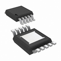
IC BUCK ADJ 2A 10MSOP
Manufacturer
National Semiconductor
Type
Step-Down (Buck)r
Datasheet
1.LM25011MYNOPB.pdf
(20 pages)
Specifications of LM25011MY/NOPB
Internal Switch(s)
Yes
Synchronous Rectifier
No
Number Of Outputs
1
Voltage - Output
2.51 ~ 40 V
Current - Output
2A
Frequency - Switching
Up to 2MHz
Voltage - Input
6 ~ 42 V
Operating Temperature
-40°C ~ 125°C
Mounting Type
Surface Mount
Package / Case
10-MSOP Exposed Pad, 10-HMSOP, 10-eMSOP
Power - Output
155mW
Primary Input Voltage
42V
No. Of Outputs
1
Output Voltage
40V
Output Current
2A
No. Of Pins
10
Operating Temperature Range
-40°C To +125°C
Msl
MSL 3 - 168 Hours
Filter Terminals
SMD
Rohs Compliant
Yes
Lead Free Status / RoHS Status
Lead free / RoHS Compliant
Other names
LM25011MYTR
Available stocks
Company
Part Number
Manufacturer
Quantity
Price
Company:

Part Number:
LM25011MY/NOPB
Manufacturer:
ATMEL
Quantity:
101
Part Number:
LM25011MY/NOPB
Manufacturer:
TI/德州仪器
Quantity:
20 000


www.national.com
inductor is rated for this peak current. The minimum ripple
current, which occurs at minimum V
p.
R
imum load current, using the minimum ripple current calcu-
lated above. The current limit threshold is the lower peak of
the inductor current waveform when in current limit (see Fig-
ure 2).
Current limit detection occurs when the voltage across the
sense resistor (R
low for tolerances, the sense resistor value is calculated using
the minimum threshold specification:
The next smaller standard value, 80 mΩ, is selected. The next
step is to ensure that sufficient ripple voltage occurs across
R
Requirements section, a minimum of 15 mVp-p voltage ripple
is required across the R
ensure the regulation circuit operates properly. The ripple
voltage is the product of the inductor ripple current amplitude
and the sense resistor value. In this case, the minimum ripple
voltage calculates to:
If the ripple voltage had calculated to less than 15 mVp-p the
inductor value would have to be reduced to increase the ripple
current amplitude. This would have required a recalculation
of I
requirement is satisfied in this case no change is necessary.
The nominal current limit threshold calculates to 1.63A. The
minimum and maximum thresholds calculate to 1.44A and
1.83A respectively, using the minimum and maximum limits
for the current limit threshold specification. The load current
is equal to the threshold current plus one half the ripple cur-
rent. Under normal load conditions, the maximum power dis-
sipation in R
maximum input voltage where the on-time duty cycle is min-
imum. In this design example, the minimum on-time duty
cycle is:
At maximum load current, the power dissipation in R
to:
When in current limit the maximum power dissipation in R
calculates to
Duty cycle is not included in this power calculation since the
on-time duty cycle is typically <5% when in current limit.
C
3.3 µF, although that is dependent on the frequency and the
desired output characteristics. C
good quality ceramic capacitor. Experimentation is usually
S
S
OUT
: The minimum current limit threshold is calculated at max-
with this value sense resistor. As mentioned in the Ripple
LIM
: The output capacitor should typically be no smaller than
P
P
V
and R
(RS)
(RS)
RIPPLE
= (1.5A)
= (1.83A + 0.472A/4)
S
S
= ΔI x R
in the above equations. Since the minimum
I
LIM
R
occurs at maximum load current, and at
S
S
) reaches the current limit threshold. To al-
2
= 1.5A – (0.2 A/2) = 1.4A
= 115 mV/1.4A = 82 mΩ
x 0.080Ω x (1 – 0.139) = 155 mW
S
S
= 200 mA x 0.080Ω = 16 mV
sense resistor during the off-time to
2
OUT
x 0.080Ω = 304 mW
IN
, calculates to 200 mAp-
should be a low ESR
S
is equal
S
14
necessary to determine the minimum value for C
nature of the load may require a larger value. A load which
creates significant transients requires a larger value for
C
C
switch current during the on-time, and limit the voltage ripple
at V
some amount of source impedance. When the buck switch
turns on, the current into V
peak of the inductor’s ripple current, then ramps up to the up-
per peak, then drops to zero at turn-off. The average current
during the on-time is the average load current. For a worst
case calculation, C
during the maximum on-time, without letting the voltage at the
VIN pin drop below a minimum operating level of 5.5V. For
this exercise 0.5V is chosen as the maximum allowed input
ripple voltage. Using the maximum load current, the minimum
value for C
where t
ripple voltage at V
sients and ringing due to long lead inductance leading to the
VIN pin. A low ESR 0.1 µF ceramic chip capacitor is recom-
mended, and C
SGND pins.
C
quality ceramic capacitor with low ESR is recommended as
C
at each turn-on. A low ESR also helps ensure a complete
recharge during each off-time.
C
time, i.e. the time for the output voltage to reach its final value
(t1 in Figure 1). For a soft-start time of 5 ms, the capacitor
value is determined from the following:
D1: A Schottky diode is recommended. Ultra-fast recovery
diodes are not recommended as the high speed transitions at
the SW pin may affect the regulator’s operation due to the
diode’s reverse recovery transients. The diode must be rated
for the maximum input voltage, the maximum load current,
and the peak current which occurs when the current limit and
maximum ripple current are reached simultaneously. The
diode’s average power dissipation is calculated from:
where V
time duty cycle.
FINAL CIRCUIT
The final circuit is shown in Figure 5, and its performance is
shown in Figure 6 and Figure 7. The current limit measured
approximately 1.62A at Vin = 8V, and 1.69A at Vin = 36V.
OUT
IN
BST
BST
SS
: The capacitor at the SS pin determines the soft-start
IN
and C
: The recommended value for C
supplies a surge current to charge the buck switch gate
, since it is assumed the voltage source feeding V
than a non-varying load.
ON
F
is the diode’s forward voltage drop, and D is the on-
BYP
is the maximum on-time, and ΔV is the allowable
IN
is calculated from:
: The purpose of C
BYP
IN
P
IN
. The purpose of C
D1
must be located close to the VIN and
must supply this average load current
= V
F
IN
x I
suddenly increases to the lower
OUT
IN
x (1 - D)
is to supply most of the
BYP
BST
is to minimize tran-
is 0.1 µF. A high
OUT
, as the
IN
has
(9)
Related parts for LM25011MY/NOPB
Image
Part Number
Description
Manufacturer
Datasheet
Request
R

Part Number:
Description:
EVAL BOARD FOR LM25011
Manufacturer:
National Semiconductor
Datasheet:
Part Number:
Description:
Mobile Pixel Link (MPL) Camera Interface Serializer and Deserializer
Manufacturer:
National Semiconductor
Datasheet:
Part Number:
Description:
National Semiconductor [8-Bit D/A Converter]
Manufacturer:
National Semiconductor
Datasheet:
Part Number:
Description:
National Semiconductor [Media Coprocessor]
Manufacturer:
National Semiconductor
Datasheet:
Part Number:
Description:
Digitally Controlled Tone and Volume Circuit with Stereo Audio Power Amplifier, Microphone Preamp Stage and National 3D Sound
Manufacturer:
National Semiconductor
Datasheet:
Part Number:
Description:
Digitally Controlled Tone and Volume Circuit with Stereo Audio Power Amplifier, Microphone Preamp Stage and National 3D Sound
Manufacturer:
National Semiconductor
Datasheet:
Part Number:
Description:
AC97 Rev 2 Codec with Sample Rate Conversion and National 3D Sound
Manufacturer:
National Semiconductor
Part Number:
Description:
Manufacturer:
National Semiconductor
Datasheet:
Part Number:
Description:
Manufacturer:
National Semiconductor
Datasheet:
Part Number:
Description:
General Purpose, Low Voltage, Low Power, Rail-to-Rail Output Operational Amplifiers
Manufacturer:
National Semiconductor
Datasheet:
Part Number:
Description:
8-bit 20 MSPS flash A/D converter.
Manufacturer:
National Semiconductor
Datasheet:
Part Number:
Description:
Low Noise Quad Operational Amplifier
Manufacturer:
National Semiconductor
Datasheet:
Part Number:
Description:
Quad Differential Line Receivers
Manufacturer:
National Semiconductor
Datasheet:
Part Number:
Description:
Quad High Speed Trapezoidal? Bus Transceiver
Manufacturer:
National Semiconductor
Datasheet: