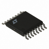
LT3825EFE#TRPBF Linear Technology, LT3825EFE#TRPBF Datasheet - Page 19

LT3825EFE#TRPBF
Manufacturer Part Number
LT3825EFE#TRPBF
Description
IC CNTRLR SYNC 16-TSSOP
Manufacturer
Linear Technology
Type
Flybackr
Datasheet
1.LT3825EFEPBF.pdf
(32 pages)
Specifications of LT3825EFE#TRPBF
Internal Switch(s)
No
Synchronous Rectifier
Yes
Number Of Outputs
1
Frequency - Switching
50kHz ~ 250kHz
Voltage - Input
12 ~ 18 V
Operating Temperature
-40°C ~ 125°C
Mounting Type
Surface Mount
Package / Case
16-TSSOP Exposed Pad, 16-eTSSOP, 16-HTSSOP
Power - Output
60W
Lead Free Status / RoHS Status
Lead free / RoHS Compliant
Current - Output
-
Voltage - Output
-
Available stocks
Company
Part Number
Manufacturer
Quantity
Price
APPLICATIONS INFORMATION
The bias current on this pin depends on the pin volt-
age and UVLO state. The change provides the user with
adjustable UVLO hysteresis. When the pin rises above
the UVLO threshold a small current is sourced out of the
pin, increasing the voltage on the pin. As the pin voltage
drops below this threshold, the current is stopped, further
dropping the voltage on UVLO. In this manner, hysteresis
is produced.
Referring to Figure 3, the voltage hysteresis at V
equal to the change in bias current times R
procedure is to select the desired V
hysteresis, V
where:
R
If we wanted a V
(5%) of hysteresis (on at 36V, off at 34.2V):
V
(3a) UV Turning ON
B
IN
R
R
I
R
R
R
R
UVLO
is then selected with the desired turn-on voltage:
A
B
B
B
A
A
=
=
=
= 1.8V
UVLO
⎛
⎜
⎝
= I
⎛
⎜
⎝
3.4μA
V
LT3825
V
1.23V
I
V
UVHYS
UVLO
IN(ON)
36V
UVLOL
UVLO
523k
I
UVLO
UVHYS
R
A
= 529k, use 523k
– 1
– 1
IN
– I
. Then:
-referred trip point of 36V, with 1.8V
⎞
⎟
⎠
(3b) UV Turning OFF
⎞
⎟
⎠
V
UVLOH
IN
= 18.5k, use 18.7k
R
R
A
B
Figure 3
UVLO
is approximately 3.4μA
LT3825
I
UVLO
IN
referred voltage
(3c) UV Filtering
A
C
. The design
UVLO
V
IN
R
R
R
3825 F03
A1
A2
B
IN
UVLO
is
Even with good board layout, board noise may cause
problems with UVLO. You can filter the divider but keep
large capacitance off the UVLO node because it will slow
the hysteresis produced from the change in bias current.
Figure 3c shows an alternate method of filtering by split-
ting the R
put more of the resistance on the UVLO side.
Converter Start-Up
The standard topology for the LT3825 utilizes a third
transformer winding on the primary side that provides both
feedback information and local V
(see Figure 4). This power “bootstrapping” improves
converter efficiency but is not inherently self-starting.
Start-up is affected with an external “trickle-charge” re-
sistor and the LT3825’s internal V
circuit. The V
to facilitate start-up.
In operation, the “trickle charge” resistor, R
nected to V
the order of 1mA to charge C
and draws only its start-up current. When C
the V
abruptly and draws its normal supply current.
CC
turn-on threshold voltage the LT3825 turns on
+
A
V
IN
IN
Figure 4. Typical Power Bootstrapping
resistor with the capacitor. The split should
CC
R
C
TR
and supplies a small current, typically on
V
TR
ON
undervoltage lockout has wide hysteresis
THRESHOLD
V
LT3825
I
V
VCC
VCC
GND
V
PG
0
CC
I
VCC
TR
PG
. Initially the LT3825 is off
CC
CC
power for the LT3825
undervoltage lockout
V
IN
3825 F04
•
•
LT3825
•
TR
TR
, is con-
reaches
19
3825fc


