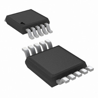
LM3481MMX/NOPB National Semiconductor, LM3481MMX/NOPB Datasheet - Page 10

LM3481MMX/NOPB
Manufacturer Part Number
LM3481MMX/NOPB
Description
IC CTLR N-CH LOW SIDE HE 10MSOP
Manufacturer
National Semiconductor
Type
Step-Up (Boost), Flyback, Sepicr
Datasheet
1.LM3481MMNOPB.pdf
(22 pages)
Specifications of LM3481MMX/NOPB
Internal Switch(s)
No
Synchronous Rectifier
No
Number Of Outputs
1
Voltage - Output
Adjustable
Current - Output
1A
Frequency - Switching
100kHz ~ 1MHz
Voltage - Input
2.97 ~ 48 V
Operating Temperature
-40°C ~ 125°C
Mounting Type
Surface Mount
Package / Case
10-MSOP, Micro10™, 10-uMAX, 10-uSOP
For Use With
LM3481EVAL - BOARD EVAL FOR LM3481
Lead Free Status / RoHS Status
Lead free / RoHS Compliant
Power - Output
-
Other names
LM3481MMX
Available stocks
Company
Part Number
Manufacturer
Quantity
Price
Company:
Part Number:
LM3481MMX/NOPB
Manufacturer:
TI
Quantity:
12 000
www.national.com
To prevent the sub-harmonic oscillations, a compensation
ramp is added to the control signal, as shown in
With the compensation ramp, ΔV
criteria are expressed by,
The compensation ramp has been added internally in the
LM3481. The slope of this compensation ramp has been se-
lected to satisfy most applications, and it's value depends on
the switching frequency. This slope can be calculated using
the formula:
In the above equation, V
compensation ramp and f
quency. Limits for V
characteristics section.
In order to provide the user additional flexibility, a patented
scheme has been implemented inside the IC to increase the
SL
have been specified in the electrical
M
C
SL
S
= V
is the controller's switching fre-
is the amplitude of the internal
FIGURE 3. Compensation Ramp Avoids Sub-Harmonic Oscillation
SL
x f
samp1
S
and the convergence
FIGURE 2. Sub-Harmonic Oscillation for D>0.5
Figure
3.
10
slope of the compensation ramp externally, if the need arises.
Adding a single external resistor, R
increases the amplitude of the compensation ramp as shown
in
FIGURE 4. Additional Slope Compensation Added Using
Where,
K = 40 µA typically and changes slightly as the switching fre-
quency changes.
on ΔV
changes.
Figure
SL
and different values of R
4.
Figure 6
External Resistor R
ΔV
SL
shows the effect the current K has
= K x R
SL
as the switching frequency
20136511
SL
SL
(as shown in
20136509
SL
201365a1
Figure
5)


