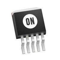
MC33167D2T ON Semiconductor, MC33167D2T Datasheet - Page 13

MC33167D2T
Manufacturer Part Number
MC33167D2T
Description
IC REG SWITCH INVERT 5A D2PAK-5
Manufacturer
ON Semiconductor
Type
Step-Down (Buck), Step-Up (Boost), Invertingr
Datasheet
1.MC33167TG.pdf
(20 pages)
Specifications of MC33167D2T
Internal Switch(s)
Yes
Synchronous Rectifier
No
Number Of Outputs
1
Voltage - Output
5 ~ 40 V
Current - Output
5A
Frequency - Switching
72kHz
Voltage - Input
7.5 ~ 40 V
Operating Temperature
-40°C ~ 85°C
Mounting Type
Surface Mount
Package / Case
D²Pak, TO-263 (5 leads + tab)
Mounting Style
SMD/SMT
Lead Free Status / RoHS Status
Contains lead / RoHS non-compliant
Power - Output
-
Lead Free Status / Rohs Status
Lead free / RoHS Compliant
Available stocks
Company
Part Number
Manufacturer
Quantity
Price
Company:
Part Number:
MC33167D2T
Manufacturer:
ON
Quantity:
347
Company:
Part Number:
MC33167D2T
Manufacturer:
MOT
Quantity:
5 510
Company:
Part Number:
MC33167D2TC
Manufacturer:
TI
Quantity:
5 510
Note that the 12 V winding is stacked on top of the 5.0 V output. This reduces the number of secondary turns and improves lead regulation. For
best auxiliary regulation, the auxiliary outputs should be less than 33% of the total output power.
T1 = Primary: Coilcraft M1496−A or General Magnetics Technology GMT−0223, 42 turns of #16 AWG on Magnetics Inc. 58350−A2 core.
T1 =
T1 = Secondary:
Heatsink = AAVID Engineering Inc. 5903B, or 5930B.
Multiple auxiliary outputs can easily be derived by winding secondaries on the main output inductor to form a transformer. The secondaries
must be connected so that the energy is delivered to the auxiliary outputs when the Switch Output turns off. During the OFF time, the voltage
across the primary winding is regulated by the feedback loop, yielding a constant Volts/Turn ratio. The number of turns for any given secondary
voltage can be calculated by the following equation:
Line Regulation
Load Regulation
Output Ripple
Short Circuit Current
Efficiency
Secondary: V
+
Tests
PWM
V
O2
O3
Oscillator
− 69 turns of #26 AWG
− 104 turns of #28 AWG
3
TOTAL
−12 V
−12 V
−12 V
−12 V
5.0 V
5.0 V
5.0 V
5.0 V
12 V
12 V
12 V
12 V
Thermal
V
V
V
V
V
V
V
in
in
in
in
in
in
in
= 15 V to 30 V, I
= 24 V, I
= 24 V, I
= 24 V, I
= 24 V, I
= 24 V, R
= 24 V, I
Figure 25. Triple Output Converter
# TURNS (SEC) +
S
R
O1
O1
O1
O1
O1
5
L
Q
MC34167, MC33167
= 0.1 W
+
= 30 mA to 3.0 A, I
= 3.0 A, I
= 3.0 A, I
= 3.0 A, I
= 3.0 A, I
http://onsemi.com
O1
ILIMIT
Reference
UVLO
0.1
= 3.0 A, I
O2
O2
O2
O2
EA
V O(SEC) ) V F(SEC)
13
= 100 mA to 250 mA, I
= 250 mA, I
= 250 mA, I
= 250 mA, I
Conditions
V O(PRI) )V F(PRI)
#TURNS (PRI)
O2
68 k
O2
= 250 mA, I
+
= 250 mA, I
O3
O3
O3
4
2
1
= 200 mA
= 75 mA to 200 mA
= 200 mA
+
24 V
V
in
O3
1000
1N5825
O3
6.8 k
= 200 mA
O3
= 200 mA
= 200 mA
1000
T1
+
MUR110
MUR110
5.0 V/3.0 A
V
O1
3.0 mV = ± 0.029%
572 mV = ± 2.4%
711 mV = ± 2.9%
1.0 mV = ± 0.009%
409 mV = ±1.5%
528 mV = ± 2.0%
75 mV
20 mV
20 mV
6.5 A
2.7 A
2.2 A
84.2%
+
+
1000
1000
pp
pp
pp
Results
−12 V/200 mA
12 V/250 mA
V
V
O3
O2


