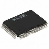
KS8993F Micrel Inc, KS8993F Datasheet - Page 42

KS8993F
Manufacturer Part Number
KS8993F
Description
IC CONV MED 10/100 3PORT 128PQFP
Manufacturer
Micrel Inc
Datasheet
1.KS8993F.pdf
(100 pages)
Specifications of KS8993F
Applications
*
Mounting Type
Surface Mount
Package / Case
128-MQFP, 128-PQFP
Number Of Primary Switch Ports
3
Internal Memory Buffer Size
32
Operating Supply Voltage (typ)
1.8/2.5/3.3V
Fiber Support
Yes
Integrated Led Drivers
Yes
Phy/transceiver Interface
MII/SNI
Power Supply Type
Analog/Digital
Package Type
PQFP
Data Rate (typ)
10/100Mbps
Vlan Support
Yes
Operating Temperature (max)
70C
Operating Temperature (min)
0C
Pin Count
128
Mounting
Surface Mount
Jtag Support
No
Operating Supply Voltage (max)
1.89/3.465V
Operating Temperature Classification
Commercial
Lead Free Status / RoHS Status
Lead free / RoHS Compliant
For Use With
KS8993F-EVAL - EVAL KIT EXPERIMENTAL KS8993F
Lead Free Status / RoHS Status
Not Compliant, Lead free / RoHS Compliant
Available stocks
Company
Part Number
Manufacturer
Quantity
Price
Part Number:
KS8993FA5
Manufacturer:
MICREL/麦瑞
Quantity:
20 000
Part Number:
KS8993FL
Manufacturer:
MICREL/麦瑞
Quantity:
20 000
2.10.1 I
With an additional I
storm protection” and “rate control” without the need of an external processor.
For KS8993F I
defined in the KS8993F register map) with the exception of the “Read Only” status registers. After the de-assertion of
reset, the KS8993F will sequentially read in the configuration data for all 110 registers, starting from register 0. The
configuration access time (t
The following is a sample procedure for programming the KS8993F with a pre-configured EEPROM:
Note: For proper operation, check to ensure that the KS8993F PWRDN input signal (pin 36) is not asserted during the
Micrel, Inc.
June 2009
1. Connect the KS8993F to the EEPROM by joining the SCL and SDA signals of the respective devices. For the
2. Enable I
3. Check to ensure that the KS8993F reset signal input, RST_N (pin 67), is properly connected to the external
4. Program the desired configuration data into the EEPROM.
5. Place the EEPROM on the board and power up the board.
6. Assert an active-low reset to the RST_N pin of the KS8993F. After reset is de-asserted, the KS8993F will
reset operation. The PWRDN input is active low.
KS8993F, SCL is pin 97 and SDA is pin 98.
reset source at the board level.
begin reading the configuration data from the EEPROM. The KS8993F will check that the first byte read from
the EEPROM is “93”.
configuration access is denied and all other data sent from the EEPROM will be ignored by the KS8993F. The
configuration access time (t
2
C Master Serial Bus Configuration
RST_N
SCL
SDA
2
C Master configuration, the EEPROM stores the configuration data for register 0 to register 109 (as
2
C master mode by setting the KS8993F strap-in pins, PS[1:0] (pins 100 and 101, respectively) to “00”.
2
C (“2-wire”) EEPROM, the KS8993F can perform more advanced switch features like “broadcast
prgm
Figure 7: KS8993F EEPROM Configuration Timing Diagram
) is less than 15 ms, as depicted in the following figure.
If this value is correct, EEPROM configuration will continue.
prgm
) is less than 15 ms.
42
t
prgm
....
....
....
<15 ms
hbwhelp@micrel.com
If not, EEPROM
or (408) 955-1690
M9999-062509
KS8993F/FL


