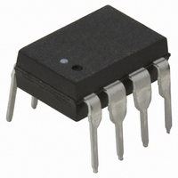
6N139-000E Avago Technologies US Inc., 6N139-000E Datasheet - Page 14

6N139-000E
Manufacturer Part Number
6N139-000E
Description
OPTOCOUPLER DARL-OUT 8-DIP
Manufacturer
Avago Technologies US Inc.
Type
Analogr
Datasheets
1.6N139-500E.pdf
(16 pages)
2.6N139-500E.pdf
(12 pages)
3.6N139-000E.pdf
(14 pages)
4.6N139-000E.pdf
(16 pages)
Specifications of 6N139-000E
Input Type
DC
Package / Case
8-DIP (0.300", 7.62mm)
Voltage - Isolation
3750Vrms
Number Of Channels
1, Unidirectional
Current - Output / Channel
60mA
Data Rate
100KBd
Propagation Delay High - Low @ If
5µs @ 500µA
Current - Dc Forward (if)
20mA
Output Type
Open Collector
Mounting Type
Through Hole
Isolation Voltage
3750 Vrms
Maximum Fall Time
25 us
Maximum Rise Time
60 us
Minimum Forward Diode Voltage
1.25 V
Output Device
Darlington With Base
Configuration
1 Channel
Current Transfer Ratio
5000 %
Maximum Baud Rate
100 KBps
Maximum Forward Diode Voltage
1.7 V
Maximum Reverse Diode Voltage
5 V
Maximum Input Diode Current
20 mA
Maximum Power Dissipation
135 mW
Maximum Operating Temperature
+ 70 C
Minimum Operating Temperature
0 C
Package Type
8-Pin DIP
No. Of Channels
1
Optocoupler Output Type
Photodarlington
Input Current
12mA
Output Voltage
18V
Opto Case Style
DIP
No. Of Pins
8
Ctr Max
5000%
Ctr Min
400%
Rohs Compliant
Yes
Lead Free Status / RoHS Status
Lead free / RoHS Compliant
Lead Free Status / RoHS Status
Lead free / RoHS Compliant, Lead free / RoHS Compliant
Other names
516-1601-5
Available stocks
Company
Part Number
Manufacturer
Quantity
Price
Company:
Part Number:
6N139-000E
Manufacturer:
AVG
Quantity:
4 684
Part Number:
6N139-000E
Manufacturer:
AVAGO/安华高
Quantity:
20 000
Figure 10. Logic low supply current vs. forward current
Figure 12. Switching test circuit
(NON-SATURATED
V
Figure 13. Test circuit for transient immunity and typical waveforms
For product information and a complete list of distributors, please go to our website:
Avago, Avago Technologies, and the A logo are trademarks of Avago Technologies Limited in the United States and other countries.
Data subject to change. Copyright © 2005-2008 Avago Technologies Limited. All rights reserved. Obsoletes AV01-0543EN
AV02-1359EN - June 24, 2008
CM
V
V
O
O
0.6
0.5
0.4
0.3
0.2
0.1
0.8
0.7
SWITCH AT A: I = 0 mA
SWITCH AT B: I = 1.6 mA
(SATURATED
0
10 V
RESPONSE)
RESPONSE)
0 V 10%
0
t
r
t
2
PHL
V
V
I
F
O
O
I
0
t
F
f
4
– FORWARD CURRENT
V
6N139 Figure 10
90%
CC
F
F
6
90%
= 18 V
10%
8
90%
1.5 V
10
V
10%
CC
10%
12
t
r
= 5 V
, t
t
90%
14
f
f
5 V
= 16 ns
V
OL
16
1.5 V
t
V
t
5 V
PLH
5 V
r
OL
6N139 Figure 13
6N139 Figure 12
V
10% DUTY CYCLE
I
FF
F
MONITOR
I/f < 100 µs
Z
I
t = 5 ns
F
O
PULSE
r
GEN.
A
= 50 Ω
B
www.avagotech.com
Figure 11. Thermal derating curve, dependence of safety limiting value
with case temperature per IEC/EN/DIN EN 60747-5-2
R
I
F
M
1
2
3
4
1000
900
800
700
600
500
400
300
200
100
0
0
PULSE GEN.
1
2
3
4
T
+
25
S
V
CM
– CASE TEMPERATURE – °C
–
50
P
I
6N139 fig 11b
S
WIDEBODY
S
(mA)
(mW)
75
8
7
6
5
100
R
CC
* INCLUDES PROBE AND
FIXTURE CAPACITANCE
8
7
6
5
125
(SEE NOTE 6)
R
150
L
0.1 µF
175
+5 V
V
R
O
L
C
L
+5 V
V
= 15 pF*
O


