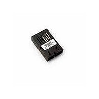
AFBR-5805Z Avago Technologies US Inc., AFBR-5805Z Datasheet - Page 8

AFBR-5805Z
Manufacturer Part Number
AFBR-5805Z
Description
TXRX ATM SONET OC3 3V SC 1X9
Manufacturer
Avago Technologies US Inc.
Series
-r
Specifications of AFBR-5805Z
Wavelength
1310nm
Applications
General Purpose
Voltage - Supply
3.3V
Connector Type
SC
Mounting Type
Through Hole
Function
Provides the system designer with products to implement a range of soluntions for multimode fiber SONET OC-3 (SDH STM-1)
Product
Transceiver
Data Rate
155 Mbps
Maximum Rise Time
3 ns/2.2 ns
Maximum Fall Time
3 ns/2.2 ns
Pulse Width Distortion
1.2 ns (Max)/1.91 ns (Max)
Maximum Output Current
50 mA
Operating Supply Voltage
3.135 V to 3.5 V or 4.75 V to 5.25 V
Maximum Operating Temperature
+ 70 C
Minimum Operating Temperature
0 C
Package / Case
SIP-9
Lead Free Status / RoHS Status
Lead free / RoHS Compliant
For Use With
Multimode Glass
Lead Free Status / RoHS Status
Lead free / RoHS Compliant, Lead free / RoHS Compliant
Available stocks
Company
Part Number
Manufacturer
Quantity
Price
Company:
Part Number:
AFBR-5805Z
Manufacturer:
Avago Technologies
Quantity:
135
Board Layout - Hole Pattern
The Avago Technologies trans ceiver complies with the
circuit board “Common Transceiver Footprint” hole
pattern defi ned in the original multisource announce-
ment which defi ned the 1 x 9 package style. This drawing
is repro duced in Figure 8 with the addition of ANSI
Y14.5M compliant dimensioning to be used as a guide in
the mechani cal layout of your circuit board.
8
(0.800)
Figure 8a. Recommended Board Layout Hole Pattern
20.32
(0.100)
2.54
TOP VIEW
(0.800)
20.32
DIMENSIONS ARE IN MILLIMETERS (INCHES)
(0.075 ± 0.004)
2 x Ø 1.9 ± 0.1
(0.032 ± 0.004)
9 x Ø 0.8 ± 0.1
Board Layout - Mechanical
For applications interested in providing a choice of either
a duplex SC or a duplex ST connector interface, while uti-
lizing the same pinout on the printed circuit board, the ST
port needs to protrude from the chassis panel a minimum
of 9.53 mm for suffi cient clearance to install the ST con-
nector.
Please refer to Figure 8a for a mechanical layout detailing
the recommended location of the duplex SC and duplex
ST trans ceiver packages in relation to the chassis panel.
0.51
0.75
Figure 8b. Recommended Common Mechanical Layout for SC and ST 1 x 9
Connectored Transceivers.
NOTE 1: MINIMUM DISTANCE FROM FRONT
OF CONNECTOR TO THE PANEL FACE.
12.0
11.1
(NOTE 1)
9.53
6.79
42.0
39.12
24.8
25.4
25.4


