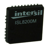
ISL8200MIRZ Intersil, ISL8200MIRZ Datasheet - Page 16

ISL8200MIRZ
Manufacturer Part Number
ISL8200MIRZ
Description
IC BUCK SYNC ADJ 10A 23-QFN
Manufacturer
Intersil
Type
Point of Load (POL) Non-Isolatedr
Datasheet
1.ISL8200MIRZ.pdf
(23 pages)
Specifications of ISL8200MIRZ
Output
0.6 ~ 6V
Number Of Outputs
1
Power (watts)
60W
Mounting Type
Surface Mount
Voltage - Input
3 ~ 20V
Package / Case
23-QFN
1st Output
0.6 ~ 6 VDC @ 10A
Size / Dimension
0.59" L x 0.59" W x 0.09" H (15mm x 15mm x 2.2mm)
Power (watts) - Rated
60W
Operating Temperature
-40°C ~ 85°C
Current - Output
10A
Voltage - Output
0.6 ~ 6 V
Frequency - Switching
700kHz ~ 1.5MHz
Synchronous Rectifier
Yes
Rohs Compliant
Yes
Lead Free Status / RoHS Status
Lead free / RoHS Compliant
3rd Output
-
2nd Output
-
Available stocks
Company
Part Number
Manufacturer
Quantity
Price
Part Number:
ISL8200MIRZ
Manufacturer:
INTERSIL
Quantity:
20 000
Power Good
The Power-Good comparators monitor the voltage on the
internal VMON1 pin. The trip points are shown in
Figure 26. PGOOD will not be asserted until after the
completion of the soft-start cycle. The PGOOD pulls low
upon both EN’s disabling it or the internal VMON1 pin’ s
voltage is out of the threshold window. PGOOD will not
be asserted until after the completion of the soft-start
cycle. PGOOD will not pull low until the fault presents for
three consecutive clock cycles.
The UV indication is not enabled until the end of
soft-start. In a UV event, if the output drops below
-13% of the target level due to some reason (cases
when EN is not pulled low) other than OV, OC, OT, and
PLL faults, PGOOD will be pulled low.
Current Share
The IAVG_CS is the current of the module. ISHARE and
ISET pins source a copy of IAVG_CS with 15µA offset,
i.e., the full scale will be 123µA.
The share bus voltage (VISHARE) set by an external
resistor (RISHARE = RISET/NCTRL) represents the
average current of all active modules. The voltage
(VISET) set by RISET represents the average current of
the corresponding module and is compared with the
share bus (VISHARE). The current share error signal
(ICSH_ER) is then fed into current correction block to
adjust each module’s PWM pulse accordingly. The current
share function provides at least 10% overall accuracy
between ICs, when using 1% resistor to sense 10mV
signal. The current share bus works for up to 6-phase.
When there is only one module in the system, the ISET
and ISHARE pins can be shorted together and
grounded via a single resistor to ensure zero share
error - a resistor value of 5k (paralleling 10k on ISET
and ISHARE) will allow operation up to the OCP level
PGOOD
FIGURE 26. POWER-GOOD THRESHOLD WINDOW
VMON1
CHANNEL 1 UV/OV
END OF SS1
16
AND
PGOOD latch off after 120% OV
PGOOD
+13%
+9%
V
-9%
-13%
+20%
REF
ISL8200M
Overvoltage Protection (OVP)
The Overvoltage (OV) protection indication circuitry
monitor the voltage on the internal VMON1 pin.
OV protection is active from the beginning of
soft-start. An OV condition (>120%) would latch IC off
(the high-side MOSFET to latch off permanently; the
low-side MOSFET turns on immediately at the time of
OV trip and then turns off permanently after the output
voltage drops below 87%). The EN and PGOOD are
also latched low at OV event. The latch condition can
be reset only by recycling V
There is another non-latch OV protection (113% of
target level). At the condition of EN low and the output
over 113% OV, the lower side MOSFET will turn on until
the output drops below 87%. This is to protect the
overall power trains in case of a single channel of a
multi-module system detecting OV. The low-side MOSFET
always turns on at the conditions of EN = LOW and the
output voltage above 113% (all EN pins are tied
together) and turns off after the output drops below
87%. Thus, in a high phase count application
(multi-module mode), all cascaded modules can latch off
simultaneously via the EN pins (EN pins are tied together
in multiphase mode), and each IC shares the same sink
current to reduce the stress and eliminate the bouncing
among phases.
Over-Temperature Protection (OTP)
When the junction temperature of the IC is greater than
+150°C (typically), EN pin will be pulled low to inform
other cascaded channels via their EN pins. All connected
ENs stay low and release after the IC’s junction
temperature drops below +125°C (typically), a +25°C
hysteresis (typically).
Overcurrent Protection (OCP)
The OCP function is enabled at startup. The module’s
output current (I
forms a voltage (V
R
internal 1.2V threshold. The Channel Overcurrent Limit
‘108µA OCP’ comparator, waits 7-cycles before
monitoring for an OCP condition.
In multi-module operation, by connecting modules’
ISHARE pin together, results in the V
representing the average current of all active channels.
The total system currents are compared with a
precision 1.2V threshold to determine the overcurrent
condition as well as each channel having additional
overcurrent trip point at 108µA with 7-cycle delay. This
scheme helps protect from damaging a module(s) in
multi-module mode by not having a single module
carrying more than 108µA. Note that it is not
necessary for the R
same level as the 108µA OCP comparator. Typically the
ISHARE pin average current protection level should be
higher than the phase current protection level. For
instance, when Channel 1 operates independently, the
ISHARE
. V
ISHARE
CS1
ISHARE
is compared with a precision
ISHARE
) plus a fixed internal 15µA offset
) across the external resistor,
to be scaled to trip at the
CC
.
ISHARE
February 26, 2010
FN6727.1


