ZUP10-20/U TDK Corporation, ZUP10-20/U Datasheet - Page 20
ZUP10-20/U
Manufacturer Part Number
ZUP10-20/U
Description
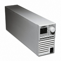
PWR SUP BENCH PROG 0-10V 200W
Manufacturer
TDK Corporation
Series
ZUPr
Type
Enclosedr
Specifications of ZUP10-20/U
Number Of Outputs
1
Efficiency
77%
Voltage - Output
0 ~ 10V
Power (watts)
200W
Applications
Commercial
Power Supply Type
Switching (Closed Frame)
Voltage - Input
85 ~ 265VAC
Mounting Type
Chassis Mount
1st Output
0 ~ 10 VDC @ 20A
Size / Dimension
13.78" L x 4.88" W x 2.76" H (350mm x 124mm x 70mm)
Power (watts) - Rated
200W
Operating Temperature
0°C ~ 50°C
Approvals
CE, EN, UL
Line Regulation
0.01%
Load Regulation
0.01%
Output Current (max)
20A
Input Voltage
85 to 265V
Output Power (max)
200W
Input Frequency
47 to 63Hz
Screening Level
Commercial
Operating Temperature Min Deg. C
0C
Operating Temperature Max Deg. C
50C
Mounting Style
Desktop
Accuracy
0.02% + 8 mV
Brand/series
ZUP
Current, Output
20 A
Display Type
Digital Meter
Power, Output
200 W
Power, Rating
200 W (Max.)
Regulation, Line
0.01% + 2 mA⁄1 mV + 0.005%
Regulation, Load
0.01% + 5 mA⁄2 mV + 0.005%
Standards
UL Listed, CE Marked
Temperature Coefficient
30 ppm⁄°C (CV)⁄100 ppm⁄°C (CC)
Temperature, Operating, Maximum
50 °C
Temperature, Operating, Minimum
0 °C
Voltage, Input
85-265 VAC
Voltage, Noise
50 mV @ 20 MHz BW
Voltage, Output
10 VDC
Voltage, Ripple
5 mV @ 5 Hz to 1 MHz
Lead Free Status / RoHS Status
Lead free / RoHS Compliant
3rd Output
-
2nd Output
-
4th Output
-
Lead Free Status / Rohs Status
RoHS Compliant part
Other names
285-1668
Q1074270
ZUP10-20/U
ZUP1020/U
Q1074270
ZUP10-20/U
ZUP1020/U


For current not shown in tables 3-1 and 3-2 use formula: Maximum length=500/(current*resistivity)
Where current is expressed in ampers and resistivity in ohms/km or ohms/1000ft.
3.7.2 Wire termination
3.7.3 Single load connection, Local Sensing
COM
VCVP
VCCP
RCCP
Fig. 3-1: Single load connection, Local Sensing
The wires should be properly terminated with terminals securely attached. DO NOT use non
terminated wires for load connection at the power supply.
Fig. 3-1 illustrates the connection of a single load to the power supply using local sensing. This
connection is made via the “External Control Connector” located on the rear panel of the power supply.
Local sensing is suitable for applications where load regulation is not critical.
- S
+S
P
EXTERNAL CONTROL
(ZUP rear panel view)
14
2
At local sensing, short between +LS or +S to -V or -S or -LS will cause damage to the
CONNECTOR
power supply. Reversing the sense wires might cause damage to the power supply
13
1
On/Off
Output Good
VRFV
VRFI
RCVP
Table 3-2: Maximum wire length for 0.5V drop on lead (in meters)
- LS
+LS
2.5
10
16
25
35
4
6
<
0.795
0.565
8.21
5.09
3.39
1.95
1.24
at local and remote sensing.
125.8
177.0
12.2
19.6
29.5
51.3
80.6
5A
Maximum length in meters -
to limit voltage drop to 0.5V or less
CAUTION
SUPPLY
POWER
14.7
25.6
40.3
62.9
88.5
10A
6.1
9.8
12.8
20.2
31.4
44.2
20A
3.0
4.9
7.4
- LS
+LS
- V
- S
+ S
- S
+V
12.6
17.7
50A
5.1
1.2
2.0
2.9
8.1
150A
0.4
0.7
1.0
1.7
2.7
4.2
5.9
+
_
LOAD
Related parts for ZUP10-20/U
Image
Part Number
Description
Manufacturer
Datasheet
Request
R

Part Number:
Description:
PWR SUP BENCH PROG 0-10V 400W
Manufacturer:
TDK Corporation
Datasheet:
Part Number:
Description:
PWR SUP BENCH PROG 0-10V 800W
Manufacturer:
TDK Corporation
Datasheet:

Part Number:
Description:
TDK DC to DC Converters, DC to AC Inverters
Manufacturer:
TDK Corporation
Datasheet:
Part Number:
Description:
TDK DC to DC Converters, DC to AC Inverters
Manufacturer:
TDK Corporation
Datasheet: