HSC-ADC-EVALCZ Analog Devices Inc, HSC-ADC-EVALCZ Datasheet - Page 27
HSC-ADC-EVALCZ
Manufacturer Part Number
HSC-ADC-EVALCZ
Description
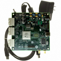
KIT EVAL ADC FIFO HI SPEED
Manufacturer
Analog Devices Inc
Datasheets
1.HSC-ADC-EVALB-DCZ.pdf
(28 pages)
2.HSC-ADC-EVALCZ.pdf
(32 pages)
3.HSC-ADC-EVALCZ.pdf
(40 pages)
Specifications of HSC-ADC-EVALCZ
Design Resources
EVALC PC Board Gerber File
Accessory Type
ADC Interface Board
Silicon Manufacturer
Analog Devices
Application Sub Type
ADC
Kit Application Type
Data Converter
Features
Buffer Memory Board For Capturing Digital Data, USB Port Interface, Windows 98, Windows 2000
Kit Contents
ADC Analyzer, Buffer Memory Board
Rohs Compliant
Yes
Lead Free Status / RoHS Status
Lead free / RoHS Compliant
For Use With/related Products
Single ADC Version
Lead Free Status / Rohs Status
Supplier Unconfirmed
Available stocks
Company
Part Number
Manufacturer
Quantity
Price
Company:

Part Number:
HSC-ADC-EVALCZ
Manufacturer:
Analog Devices Inc
Quantity:
135


HILBERT TRANSFORM
Hilbert Transform performs a Hilbert transform on a real
waveform to compute the resulting complex waveform. The
output is the complex waveform that consists of the real input
waveform as I data, along with its Q data counterpart.
INPUT FORMATTER
Input Formatter takes data and converts it from an integer data
type to the normalized format accepted by most VisualAnalog
processing blocks. To set the format, click Settings.
This component converts integer input data from Gray Code,
Unsigned Offset, Two’s Complement, and Signed into nor
malized signed data. The resolution and bit alignment should
match that of the input data. See the ADC Model, ADC Data
Capture, FIFO4.X Interface, and Pattern Loader sections to
determine how best to set these parameters.
INVERSE FFT
Inverse FFT translates real or complex frequency data to a real
or complex time waveform.
Figure 62. Input Formatter Settings
Figure 60.Hilbert Transform
Figure 61. Input Formatter
Figure 63. Inverse FFT
Rev. 0 | Page 27 of 40
INVERSE SINC
Inverse Sinc applies the inverse sinc to the time domain series.
Both input and output are time domain series. This feature is
useful to correct the magnitude roll-off vs. frequency caused when
digital data is converted back into the analog domain. This
function provides maximum flatness of the largest possible range.
I vs. Q
The I vs. Q component formats complex time-domain input
data into a form that represents a constellation. This component
outputs analysis data that, when plotted, appears as Q data on
the y-axis and as I data on the x-axis.
LOGIC ANALYSIS
Logic Analysis formats the data for display as a logic analysis.
Set the High Bit and Low Bit fields to represent the range of
valid bits.
When using VisualAnalog processed data, the Output
Formatter should precede Logic Analysis to convert the data
to a particular numeric format and resolution. If the data is
already in integer format from a file, ADC Model, or ADC
Data Capture, Output Formatter does not need to precede
this component.
Figure 66. Logic Analysis and Settings Form
Figure 64. Inverse Sinc
Figure 65. I vs. Q
AN-905
Related parts for HSC-ADC-EVALCZ
Image
Part Number
Description
Manufacturer
Datasheet
Request
R

Part Number:
Description:
KIT EVAL ADC FIFO DUAL-CH USB HS
Manufacturer:
Analog Devices Inc
Datasheet:

Part Number:
Description:
KIT EVAL ADC USB FIFO HI-SPEED
Manufacturer:
Analog Devices Inc
Datasheet:

Part Number:
Description:
BOARD FPGA OCTAL LVDS FOR ADC
Manufacturer:
Analog Devices Inc
Datasheet:
Part Number:
Description:
KIT EVAL FOR SINGLE CHAN HSC ADC
Manufacturer:
Analog Devices Inc

Part Number:
Description:
KIT EVAL FOR DUAL ADC/CONV
Manufacturer:
Analog Devices Inc
Datasheet:
Part Number:
Description:
KIT EVAL ADC USB FIFO HI-SPEED
Manufacturer:
Analog Devices Inc
Datasheet:

Part Number:
Description:
KIT EVAL ADC USB FIFO HI-SPEED
Manufacturer:
Analog Devices Inc
Datasheet:
Part Number:
Description:
KIT EVAL ADC FIFO DUAL-CH USB HS
Manufacturer:
Analog Devices Inc
Datasheet:
Part Number:
Description:
BOARD FPGA QUAD LVDS FOR ADC
Manufacturer:
Analog Devices Inc
Datasheet:
Part Number:
Description:
Adapter For AD922x Family
Manufacturer:
Analog Devices Inc
Datasheet:
Part Number:
Description:
Interposer Quad/octal ADCs
Manufacturer:
Analog Devices Inc
Datasheet:

Part Number:
Description:
±1.7g Dual-Axis IMEMS Accelerometer Evaluation Board
Manufacturer:
Analog Devices Inc
Datasheet:

Part Number:
Description:
IC MULTIPLIER ANALOG 8-SOIC T/R
Manufacturer:
Analog Devices Inc
Datasheet:
Part Number:
Description:
IC ANALOG MULTIPLIER 8-DIP
Manufacturer:
Analog Devices Inc
Datasheet: