MCP402XEV Microchip Technology, MCP402XEV Datasheet
MCP402XEV
Specifications of MCP402XEV
Available stocks


Related parts for MCP402XEV

MCP402XEV Summary of contents
Page 1
... Microchip Technology Inc. MCP401X/2X Digital Potentiometer Evaluation Board User’s Guide DS51546B ...
Page 2
... PowerMate, PowerTool, rfLAB, rfPICDEM, Select Mode, Smart Serial, SmartTel, Total Endurance and WiperLock are trademarks of Microchip Technology Incorporated in the U.S.A. and other countries. SQTP is a service mark of Microchip Technology Incorporated in the U.S.A. All other trademarks mentioned herein are property of their respective companies. ...
Page 3
... A.6 MCP402X Board Layout – Bottom Layer + Silk-screen Appendix B. Bill Of Materials (BOM) Appendix C. Using the BFMP Programmer to Power the Board C.1 Powering the Board Using the BFMP Programmer ..................................... 25 Appendix D. Potential Programming Issue of the MCP402XEV D.1 Introduction .................................................................................................. 27 Appendix E. 00066_MCP402XEV.ASM Source Code E.1 Introduction .................................................................................................. 29 Worldwide Sales and Service .................................................................................... 42 © ...
Page 4
... MCP401X/2X Evaluation Board User’s Guide NOTES: DS51546B-page iv © 2005 Microchip Technology Inc. ...
Page 5
... Appendix C. “Using the BFMP Programmer to Power the Board” – Shows how to interface the BFMP board with the MCP402X Digital Potentiometer Evalu- ation Board. • Appendix D. “Potential Programming Issue of the MCP402XEV” – Discusses possible programming issues with Rev 1 and Rev 2 of the MCP402X Digital Potentiometer Evaluation Board. ...
Page 6
... A hexadecimal number where 0xFFFF, 0x007A hexadecimal digit Optional arguments mcc18 [options] file [options] Choice of mutually exclusive errorlevel {0|1} arguments selection Replaces repeated text var_name [, var_name...] Represents code supplied by void main (void) user { ... } © 2005 Microchip Technology Inc. Examples ® IDE User’s Guide ...
Page 7
... Added Appendix C. “Using the BFMP Programmer to Power the Board” - Programming the MCP402X Digital Potentiometer Evaluation Board • Added Appendix D. “Potential Programming Issue of the MCP402XEV”- A description of potential programming issues (and their solutions) with the MCP402X Digital Potentiometer Evaluation Board Revision A (April 2005) • ...
Page 8
... MCP401X/2X Evaluation Board User’s Guide NOTES: DS51546B-page 4 © 2005 Microchip Technology Inc. ...
Page 9
... SOT-23-6 MCP4012-XXX/OT devices • SOT-23-6 MCP4013-XXX/OT devices • SOT-23-5 MCP4014-XXX/OT devices In addition to supporting the MCP401X/2X, the MCP402XEV also utilizes the SOT-23-6 PIC10F20X microcontroller. The PIC10F20X is supplied with example firmware that debounces the INCR and DECR push buttons and generates the simple U/D protocol required by the MCP401X/2X to increment and decrement the potentiometer’ ...
Page 10
... INCLUDES This MCP402X Digital Potentiometer Evaluation Board Kit includes: • One populated Printed Circuit Board (PCB) - MCP4021-103/OT - PIC10F206-I/OT with 00066_MCP402XEV.HEX programmed into memory - Two push button switches: one for Increment commands (INCR), one for Decrement commands (DECR) - Decoupling capacitors - 5 resistors to isolate the switches and create a voltage divider with the MCP4021-103/OT • ...
Page 11
... DECR button operation can be detected by the PIC10F20X to generate Decrement commands (move wiper toward terminal B) • Button sequence instructions are printed on the back of the PCB Appendix A.2 “Schematic” illustrates the schematic for the MCP402XEV. Note: The PIC10F20X firmware (00066_MCP402XEV.HEX) must be programmed into the microcontroller before the MCP402XEV is functional. ...
Page 12
... Increment and Decrement commands. Since this device is nonvolatile, the WiperLock™ Technology feature is not present. DS51546B-page 8 WINDOWED POTENTIOMETER – VOLTAGE DIVIDER CALCULATION 5.0V d 10k DD wb ------------------------------------------ - --------------------------------------------------------------------- wiper 2.5k nom Where the wiper setting ( 2.5k + 2.5k + 10k © 2005 Microchip Technology Inc. ...
Page 13
... B to GND. 3: The MCP4014 has high-voltage tolerant pins and, therefore, accepts high-voltage Increment and Decrement commands. Since this device is nonvolatile, the WiperLock™ Technology feature is not present. © 2005 Microchip Technology Inc. Installation and Operation GROUNDED POTENTIOMETER – VOLTAGE DIVIDER CALCULATION ...
Page 14
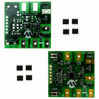
... Increment (INCR) Switch Resistor VDD) Baseline Flash MCU Programmer (BFMP) Interface Resistor GND) Decrement (DECR) Switch FIGURE 2-1: Digital Potentiometer Evaluation Board Overview. DS51546B-page 10 Digital Digital Potentiometer Potentiometer Node A Pad Node B Pad © 2005 Microchip Technology Inc using Digital Potentiometer Wiper W Pad ...
Page 15
... MCP4021 is utilized, the output range will be approximately 0.83V to 4.17V. • MCP4021 is utilized, the output range will be approximately 0.23V to 4.77V. © 2005 Microchip Technology Inc. Installation and Operation and the “–” to GND. DD POPULATED PCB – VOLTAGE DIVIDER CALCULATION ...
Page 16
... MCP401X/2X Evaluation Board User’s Guide 2.3.2 MCP402X Digital Potentiometer Evaluation Board Firmware Operation The 00066_MCP402XEV.HEX firmware programmed into the PIC10F20X provides a very simple interface to operate the MCP402X digital potentiometer. There are ten basic commands supported for the user to exercise the MCP402X digital potentiometer. ...
Page 17
... MCP401X/2X Evaluation Board User’s Guide INCR/DECR will MCP401x “locked” is Wiper when Works “unlocked” “locked” pins? U/D and CS on Voltage High EEPROM in Value Wiper Saves DS51546B-page 13 © 2005 Microchip Technology Inc. ...
Page 18
... Voltage equals approximately 3.33V. This shows that the MCP4021 retained the last selected wiper setting. On the Digital Potentiometer Evaluation Board: Wiper is incremented one position and the wiper is locked (WiperLock Technology is enabled). On DMM: Voltage equals approximately 3.38V. © 2005 Microchip Technology Inc. ...
Page 19
... Turn off/disconnect power supply the Digital Potentiometer Evaluation Board: Re-apply power to Digital Potentiometer Evaluation Board. © 2005 Microchip Technology Inc. Installation and Operation Result On the Digital Potentiometer Evaluation Board: Wiper is NOT moved due to the wiper being locked (WiperLock™ Technology is enabled). ...
Page 20
... Voltage Voltage Position (V) (V) 2.526 48 3.373 2.579 49 3.426 2.632 50 3.479 2.685 51 3.532 2.738 52 3.585 2.791 53 3.638 2.844 54 3.690 2.897 55 3.743 2.950 56 3.796 3.003 57 3.849 3.056 58 3.902 3.108 59 3.955 3.161 60 4.008 3.214 61 4.061 3.267 62 4.114 (2) 3.320 63 4.167 © 2005 Microchip Technology Inc. ...
Page 21
... V = 5.0V). Utilizing such a charge pump requires special attention to the timing of the DD CS & U/D signals. Refer to the comments in the 00066_MCP402XEV.ASM source code for more details on the firmware’s operation. Refer to Appendix E. “00066_MCP402XEV.ASM Source Code”. © 2005 Microchip Technology Inc. Installation and Operation ...
Page 22
... MCP401X/2X Evaluation Board User’s Guide NOTES: DS51546B-page 18 © 2005 Microchip Technology Inc. ...
Page 23
... Board. The populated PCB was built using this schematic. • Board Layout – Top Layer + Silk-screen • Board Layout – Top Silk-Screen • Board Layout – Bottom Layer + Silk-screen • Board Layout – Bottom Layer © 2005 Microchip Technology Inc. MCP401X/2X EVALUATION BOARD USER’S GUIDE DS51546B-page 19 ...
Page 24
... MCP401X/2X Evaluation Board User’s Guide A.2 SCHEMATIC DS51546B-page 20 © 2005 Microchip Technology Inc. ...
Page 25
... A.3 MCP402X BOARD LAYOUT – TOP LAYER + SILK-SCREEN A.4 MCP402X BOARD LAYOUT – BOTTOM LAYER © 2005 Microchip Technology Inc. Schematic and Layouts DS51546B-page 21 ...
Page 26
... MCP401X/2X Evaluation Board User’s Guide A.5 MCP402X BOARD LAYOUT – TOP SILK-SCREEN A.6 MCP402X BOARD LAYOUT – BOTTOM LAYER + SILK-SCREEN DS51546B-page 22 © 2005 Microchip Technology Inc. ...
Page 27
... U3 PIC10F206, 6-Pin, 8-Bit Flash Microcontrollers 1 U2 MCP4022/23/24 5/6 Pin Digital Potentiometer (Optional) 7 A,B,W,VDD,GND, Test Point PC Compact SMT U/D,CS (Optional) © 2005 Microchip Technology Inc. MCP401X/2X EVALUATION BOARD USER’S GUIDE Description Manufacturer ® Kemet ® Panasonic ECG ON Semiconductor BAV99 Panasonic Corporation – ...
Page 28
... MCP401X/2X Evaluation Board User’s Guide NOTES: DS51546B-page 24 © 2005 Microchip Technology Inc. ...
Page 29
... The BFMP programmer (PG164101) uses a 6-pin interface for programming. The PICkit™ 2 Flash Starter Kit (PG164120 or DV164120) uses the same interface. The MCP402X Digital Potentiometer Evaluation Board (MCP402XEV) plugs into the BFMP (or PICkit™ 2 Flash Starter Kit) in the orientation shown in Figure C-1. ...
Page 30
... When programming the MCP402X Digital Potentiometer Evaluation Board, under “Board Controls” NOT check Device Power. This ensures that the PIC10F206 is only powered during the programming cycle. DS51546B-page 26 Ensure Device Power IS checked and 2.5 kHz Osc is NOT checked. © 2005 Microchip Technology Inc. ...
Page 31
... Appendix D. Potential Programming Issue of the MCP402XEV D.1 INTRODUCTION When programming the MCP402XEV with a Microchip programmer (such as the BPMF ® or MPLAB ICD 2), the PIC10F206 may not program correctly due to the load on the ICSPDAT pin. This issue relates to PCBs marked 104-00066 and 104-00066R2. ...
Page 32
... MCP401X/2X Evaluation Board User’s Guide FIGURE D-2: MCP402XEV R2 Schematic PCB R2, ECN #1. DS51546B-page 28 This is the node that needs to be open when programming. JP1 C2 © 2005 Microchip Technology Inc. ...
Page 33
... This appendix documents the example PIC10F20X source code used on the populated PCB. The source code is described in detail by the comments within the.ASM file. The 00066_MCP402XEV.ASM, PIC10F206.INC and MCP402XEV.HEX files can be found on the Microchip web site (www.microchip.com) and on the included CD. The software supplied herewith by Microchip Technology Incorporated (the “Company”) is intended and supplied to you, the Company’ ...
Page 34
... Source Code TABLE E-1: 00066_MCP402XEV.ASM SOURCE CODE (CONTINUED) ;********************************************************************************************** ; Connections/Schematic ;********************************************************************************************** ; ; MCP pin MCP4021 MCP4022 ; _______ _______ _______ ; 1 Vdd Vdd ; 2 Vss Vss ; MCP402x PIC10F206 ; _______ _________ ; Vdd Vdd ; Vss Vss ; GP0/ICSPDAT (int pu) ; U/D GP1/ICSPCLK (int pu GP2/OSCOUT ; - GP3/Vpp (int pu) ; ;********************************************************************************************** ...
Page 35
... Source Code TABLE E-1: 00066_MCP402XEV.ASM SOURCE CODE (CONTINUED) ;********************************************************************************************** ; General Pupose Register Definitions ;********************************************************************************************** GPRS UDATA State res 1 ; variable to track the “state” value ; this code functions as a state machine ; bits 3:0 stores the state 0-15 indicator ; bits 7:6 stores the debounced button states ...
Page 36
... Source Code TABLE E-1: 00066_MCP402XEV.ASM SOURCE CODE (CONTINUED) ButtonCheck ; Debounce Buttons btfss PowerDown ; If pulled low, put uC to SLEEP goto LowPowerMode bsf UP_State bsf DOWN_State ; initialize Button_State to indicate no button pressed movlw .50 ; debounce the buttosns for 50mS to see if pressed movwf Exit movlw .40 ...
Page 37
... Source Code TABLE E-1: 00066_MCP402XEV.ASM SOURCE CODE (CONTINUED) Loop1_2sec call GPIO_TestDOWN ; make GP0/DECR/CS an input (w/pu enabled) movlw .5 ; 5ms delay call VAR1000TcyDELAY btfss DOWN ; if DOWN gets pressed, exit retlw .1 call GPIO_TestUP ; make GP1/INCR/UD an input (w/pu enabled) movlw .5 ; 5ms delay call VAR1000TcyDELAY ...
Page 38
... Source Code TABLE E-1: 00066_MCP402XEV.ASM SOURCE CODE (CONTINUED) State4 ; LV Decrement call InitGPIO ; make GP0/DECR/CS & GP1/INCR/UD outputs, block undesired U/D commands movlw .1 call LV_Decrement clrf State retlw .4 State5 ; Both buttons pressed movlw .200 ; 200x10mS = 2s movwf Exit Loop5_2sec call GPIO_TestUP ; make GP1/INCR/UD an input (w/pu enabled) movlw ...
Page 39
... Source Code TABLE E-1: 00066_MCP402XEV.ASM SOURCE CODE (CONTINUED) HV_DecrExit clrwdt call GPIO_TestUP ; make GP1/INCR/UD an input (w/pu enabled) movlw .10 call VAR1000TcyDELAY ; add a 10mS delay for settling time btfss gets released, exit goto HV_DecrExit call GPIO_TestDOWN ; make GP0/DECR/CS an input (w/pu enabled) movlw ...
Page 40
... Source Code TABLE E-1: 00066_MCP402XEV.ASM SOURCE CODE (CONTINUED) ;*********************************************************************************************** ; State Machine Subroutines ;*********************************************************************************************** DetermineState swapf State,f rrf State,f rrf State,w andlw b’00111111’ ; mask invalid states addwf PCL,f S0_00 retlw .0 ; both buttons pressed at same time, shouldn’t be here S0_01 retlw . button pressed, change state ...
Page 41
... Source Code TABLE E-1: 00066_MCP402XEV.ASM SOURCE CODE (CONTINUED) S13_10 retlw .0 ; shouldn’t be here, reset state S13_11 retlw .0 ; shouldn’t be here, reset state S14_00 retlw .0 ; shouldn’t be here, reset state S14_01 retlw .0 ; shouldn’t be here, reset state S14_10 retlw .0 ; shouldn’t be here, reset state ...
Page 42
... Source Code TABLE E-1: 00066_MCP402XEV.ASM SOURCE CODE (CONTINUED) ;*********************************************************************************************** ; Button Isolation Subroutines ;*********************************************************************************************** ; Low Voltage Increment & Decrement Subroutines ;*********************************************************************************************** LV_Increment movwf Exit ; load the loop counter bsf UD goto $+1 ; creates a 3us total delay bcf CS movlw .100 ; 5*100 = 500us delay to pull down CS movwf DLYCNT1 ...
Page 43
... Source Code TABLE E-1: 00066_MCP402XEV.ASM SOURCE CODE (CONTINUED) ;*********************************************************************************************** ; High Voltage Increment & Decrement Subroutines ;*********************************************************************************************** HV_Increment_WL_Disable movwf Exit ; load the loop counter bsf UD goto $+1 ; creates a 3us total delay bsf HV_CS ; starts 1Mhz Charge Pump movlw .100 ; 5*100 = 500us delay for Charge Pump ramp time ...
Page 44
... Source Code TABLE E-1: 00066_MCP402XEV.ASM SOURCE CODE (CONTINUED) DLOOP_HVIWL clrwdt ;or NOP nop decfsz DLYCNT1,f goto DLOOP_HVIWL bcf UD goto $+1 ; creates a 3us total delay bsf UD goto $+1 ; creates a 3us total delay bcf UD goto $+1 ; creates a 3us total delay bcf HV_CS ; shut off 1Mhz Charge Pump ...
Page 45
... Source Code TABLE E-1: 00066_MCP402XEV.ASM SOURCE CODE (CONTINUED) ;************ ; VARIABLE 5 Tcy DELAY UP TO 256*5Tcy+5Tcy ; DLYCNT1 = W ; DELAY = T DLYCNT1 - 1) + CALL + RETLW ; ; ex. To create a 250us delay, (250/5)- movlw .49 ;load .49 into WREG ; call VAR5TcyDELAY ;call VAR5TcyDELAY ;************ ; The value the time of the CALL = x. VAR5TcyDELAY movwf DLYCNT1 ...
Page 46
... Fax: 886-3-572-6459 Taiwan - Kaohsiung Tel: 886-7-536-4818 Fax: 886-7-536-4803 Taiwan - Taipei Tel: 886-2-2500-6610 Fax: 886-2-2508-0102 Thailand - Bangkok Tel: 66-2-694-1351 Fax: 66-2-694-1350 © 2005 Microchip Technology Inc. EUROPE Austria - Wels Tel: 43-7242-2244-399 Fax: 43-7242-2244-393 Denmark - Copenhagen Tel: 45-4450-2828 Fax: 45-4485-2829 France - Paris Tel: 33-1-69-53-63-20 ...