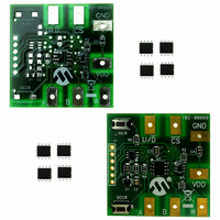
MCP402XEV Microchip Technology, MCP402XEV Datasheet - Page 18

MCP402XEV
Manufacturer Part Number
MCP402XEV
Description
BOARD EVAL FOR MCP402X
Manufacturer
Microchip Technology
Datasheet
1.MCP402XEV.pdf
(46 pages)
Specifications of MCP402XEV
Main Purpose
Digital Potentiometer
Embedded
Yes, MCU, 8-Bit
Utilized Ic / Part
MCP4021
Primary Attributes
1 Single Pot, 10 kOhm, 64 Tap, Non Volatile
Secondary Attributes
2.7 ~ 5.5 V, 150 ppm/°C
Processor To Be Evaluated
MCP402X
Lead Free Status / RoHS Status
Lead free / RoHS Compliant
Lead Free Status / RoHS Status
Lead free / RoHS Compliant, Lead free / RoHS Compliant
Available stocks
Company
Part Number
Manufacturer
Quantity
Price
Company:
Part Number:
MCP402XEV
Manufacturer:
MICROCHIP
Quantity:
12 000
MCP401X/2X Evaluation Board User’s Guide
TABLE 2-2:
DS51546B-page 14
Step Action
1
2
3
4
5
6
7
8
9
10
Power up the populated Digital Potentiometer
Evaluation Board.
Voltage calculations use a system voltage of 5V.
Board can be powered via a valid voltage (such as 5V)
on the VDD and GND PCB Pads, or by connecting a
BFMP programmer that is connected to an active PC’s
USB port (powered via the USB connection).
Set DMM to measure the required voltage range
(0V to 5.5V).
Connect the DMM ground connection to the
evaluation board GND terminal and the DMM V/
connection to terminal W of the evaluation board.
Turn on DMM.
On the Digital Potentiometer Evaluation Board:
Implement Command #5 (see Table 2-1).
On the Digital Potentiometer Evaluation Board:
Implement Command #4 (see Table 2-1).
On the Digital Potentiometer Evaluation Board:
Implement Command #6 (see Table 2-1).
On the Digital Potentiometer Evaluation Board:
Implement Command #6 (see Table 2-1) 15 more
times.
On the Digital Potentiometer Evaluation Board:
Turn off/disconnect power supply.
On the Digital Potentiometer Evaluation Board:
Reapply power to Digital Potentiometer Evaluation
Board.
On the Digital Potentiometer Evaluation Board:
Implement Command #3 (see Table 2-1).
MEASURING RATIOMETRIC VOLTAGE
2.3.3
Table 2-2 provides step-by-step instructions to perform a demonstration of the
MCP402X Digital Potentiometer Evaluation Board. Measuring Ratiometric Voltage
Running the Ratiometric Voltage Demo
Result
—
—
On DMM:
DMM will display the voltage determined by the
current non-volatile setting of the wiper.
On the Digital Potentiometer Evaluation Board:
WiperLock™ Technology is disabled and the wiper is
incremented from power-on position.
On DMM:
Voltage increments approximately 0.05V.
On the Digital Potentiometer Evaluation Board:
Wiper is forced to the full-scale position
(Wiper W = node A).
On DMM:
Voltage equals approximately 4.17V.
On the Digital Potentiometer Evaluation Board:
Wiper is decremented one position from the full-scale
position.
On DMM:
Voltage equals approximately 4.12V.
On the Digital Potentiometer Evaluation Board:
Wiper is decremented to the 25% position from
node A (full-scale) to node B (zero-scale).
On DMM:
Voltage equals approximately 3.33V.
On DMM:
Voltage equals approximately 0V.
On DMM:
Voltage equals approximately 3.33V. This shows that
the MCP4021 retained the last selected wiper setting.
On the Digital Potentiometer Evaluation Board:
Wiper is incremented one position and the wiper is
locked (WiperLock Technology is enabled).
On DMM:
Voltage equals approximately 3.38V.
© 2005 Microchip Technology Inc.


