AT89STK-05 Atmel, AT89STK-05 Datasheet - Page 11
AT89STK-05
Manufacturer Part Number
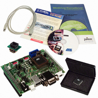
AT89STK-05
Description
KIT STARTER FOR AT89C5131
Manufacturer
Atmel
Specifications of AT89STK-05
Main Purpose
*
Embedded
*
Utilized Ic / Part
AT89C5131
Primary Attributes
*
Secondary Attributes
*
Processor To Be Evaluated
AT89C5131A
Interface Type
RS-232, USB
Lead Free Status / RoHS Status
Contains lead / RoHS non-compliant


3.1
3.2
AT89C5131A Starter Kit Hardware User Guide
In-System
Programming
Using a
Programmer
The user memory of the AT89C5131A part can be programmed using the ISP mode of
the device. In order to enter in ISP mode, first select the high pin count mode (PSEN) or
the low pin count mode (P1.0) using the ISP switch (SW2).
To enter in ISP mode, press both the RESET (SW3) and ISP (SW4) buttons simulta-
neously. First release the RESET button and then the ISP button. The device enters in
ISP mode.
ISP can then be performed using the USB bus (or with the peripheral corresponding
with the bootloader version). The user may need to re-enumerate the USB bus using the
USB UNLOAD button (SW1) if the USB cable is already connected.
The AT89C5131A microcontroller can also be programmed using a programmer with
the J3 connector. Connect all required signals between the programmer and the J3 con-
nector and remove the J7 jumper to disconnect the EA circuitry. No clock should be
enabled on the board, except the clock coming from the J3 connector.
Figure 3-1. J3 Connector Schematic
J3
Device Programming
1
2
3
4
5
6
7
8
9
10
VCC
VSS
XTAL1
VSS
NC
RST
P3.2 (Test0)
VSS
P3.4 (Test1)
VSS
Section 3
Rev. 4245A–USB–11/04
3-9
Related parts for AT89STK-05
Image
Part Number
Description
Manufacturer
Datasheet
Request
R

Part Number:
Description:
KIT EVAL APPL MASS STORAGE
Manufacturer:
Atmel
Datasheet:

Part Number:
Description:
KIT DEMOBOARD 8051 MCU W/CAN
Manufacturer:
Atmel
Datasheet:

Part Number:
Description:
KIT STARTER FOR AT83C24
Manufacturer:
Atmel
Datasheet:

Part Number:
Description:
EVAL BOARD FOR AT83C26
Manufacturer:
Atmel
Datasheet:

Part Number:
Description:
KIT STARTER FOR MCU AT8XC5122/23
Manufacturer:
Atmel
Datasheet:

Part Number:
Description:
KIT STARTER FOR AT89C51RX2
Manufacturer:
Atmel
Datasheet:


Part Number:
Description:
8-Bit Microcontroller with 4K Bytes Flash
Manufacturer:
ATMEL Corporation
Datasheet:

Part Number:
Description:
DEV KIT FOR AVR/AVR32
Manufacturer:
Atmel
Datasheet:
Part Number:
Description:
INTERVAL AND WIPE/WASH WIPER CONTROL IC WITH DELAY
Manufacturer:
ATMEL Corporation
Datasheet:
Part Number:
Description:
Low-Voltage Voice-Switched IC for Hands-Free Operation
Manufacturer:
ATMEL Corporation
Datasheet:
Part Number:
Description:
MONOLITHIC INTEGRATED FEATUREPHONE CIRCUIT
Manufacturer:
ATMEL Corporation
Datasheet:
Part Number:
Description:
AM-FM Receiver IC U4255BM-M
Manufacturer:
ATMEL Corporation
Datasheet:
Part Number:
Description:
Monolithic Integrated Feature Phone Circuit
Manufacturer:
ATMEL Corporation
Datasheet: