AT89STK-05 Atmel, AT89STK-05 Datasheet - Page 7
AT89STK-05
Manufacturer Part Number
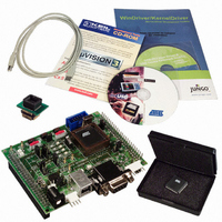
AT89STK-05
Description
KIT STARTER FOR AT89C5131
Manufacturer
Atmel
Specifications of AT89STK-05
Main Purpose
*
Embedded
*
Utilized Ic / Part
AT89C5131
Primary Attributes
*
Secondary Attributes
*
Processor To Be Evaluated
AT89C5131A
Interface Type
RS-232, USB
Lead Free Status / RoHS Status
Contains lead / RoHS non-compliant


2.3
2.3.1
2.3.2
2.3.3
2.3.4
AT89C5131A Starter Kit Hardware User Guide
C51 Standard
Settings
Reset
Clock
EA
INT0
The external Reset push-button (SW3) is provided to easily generate a warm reset. This
button is used for ISP process. The Reset applied is active low.
A crystal can be easily installed on the Y1 socket. The clock can also be provided using
the J8 connector instead of the crystal.
Note:
Place a jumper on the EA connector (J10) to force the EA pin to ground and execute
external code. Otherwise internal code will be executed.
Figure 2-3. EA Circuitry
In order to use the on-board INT0 circuitry, connect the J7 Jumper to the AT89C5131A.
When you press the INT0 button (SW5), the P3.2 pin will go low which induces an inter-
rupt event.
Note:
Figure 2-4. INT0 Circuitry
Remove the clock generators before the using the programmer.
Remove the J7 jumper before using the programmer. Otherwise the program-
mer will not function.
Hardware Description
4245A–USB–11/04
2-5
Related parts for AT89STK-05
Image
Part Number
Description
Manufacturer
Datasheet
Request
R

Part Number:
Description:
KIT EVAL APPL MASS STORAGE
Manufacturer:
Atmel
Datasheet:

Part Number:
Description:
KIT DEMOBOARD 8051 MCU W/CAN
Manufacturer:
Atmel
Datasheet:

Part Number:
Description:
KIT STARTER FOR AT83C24
Manufacturer:
Atmel
Datasheet:

Part Number:
Description:
EVAL BOARD FOR AT83C26
Manufacturer:
Atmel
Datasheet:

Part Number:
Description:
KIT STARTER FOR MCU AT8XC5122/23
Manufacturer:
Atmel
Datasheet:

Part Number:
Description:
KIT STARTER FOR AT89C51RX2
Manufacturer:
Atmel
Datasheet:


Part Number:
Description:
8-Bit Microcontroller with 4K Bytes Flash
Manufacturer:
ATMEL Corporation
Datasheet:

Part Number:
Description:
DEV KIT FOR AVR/AVR32
Manufacturer:
Atmel
Datasheet:
Part Number:
Description:
INTERVAL AND WIPE/WASH WIPER CONTROL IC WITH DELAY
Manufacturer:
ATMEL Corporation
Datasheet:
Part Number:
Description:
Low-Voltage Voice-Switched IC for Hands-Free Operation
Manufacturer:
ATMEL Corporation
Datasheet:
Part Number:
Description:
MONOLITHIC INTEGRATED FEATUREPHONE CIRCUIT
Manufacturer:
ATMEL Corporation
Datasheet:
Part Number:
Description:
AM-FM Receiver IC U4255BM-M
Manufacturer:
ATMEL Corporation
Datasheet:
Part Number:
Description:
Monolithic Integrated Feature Phone Circuit
Manufacturer:
ATMEL Corporation
Datasheet: