AD9516-3/PCBZ Analog Devices Inc, AD9516-3/PCBZ Datasheet - Page 47
AD9516-3/PCBZ
Manufacturer Part Number
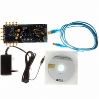
AD9516-3/PCBZ
Description
BOARD EVAL FOR AD9516-3 2.0GHZ
Manufacturer
Analog Devices Inc
Specifications of AD9516-3/PCBZ
Main Purpose
Timing, Clock Generator
Embedded
No
Utilized Ic / Part
AD9516-3
Primary Attributes
2 Inputs, 14 Outputs, 2GHz VCO
Secondary Attributes
CMOS, LVDS, LVPECL Output Logic, ADIsimCLK™ Graphical User Interface
Silicon Manufacturer
Analog Devices
Application Sub Type
PLL Clock Synthesizer
Kit Application Type
Clock & Timing
Silicon Core Number
AD9516-0, AD9516-1, AD9516-2
Silicon Family Name
AD9516-X
Rohs Compliant
Yes
Lead Free Status / RoHS Status
Lead free / RoHS Compliant


INPUT TO CHANNEL DIVIDER
A sync operation brings all outputs that have not been excluded
(by the nosync bit) to a preset condition before allowing the
outputs to begin clocking in synchronicity. The preset condition
takes into account the settings in each of the channel’s start high
bit and its phase offset. These settings govern both the static
state of each output when the SYNC operation is happening and
the state and relative phase of the outputs when they begin
clocking again upon completion of the SYNC operation.
Between outputs and after synchronization, this allows for the
setting of phase offsets.
The AD9516 outputs are in pairs, sharing a channel divider per
pair (two pairs of pairs, four outputs, in the case of CMOS). The
synchronization conditions apply to both outputs of a pair.
SYNC PIN
SYNC PIN
INPUT TO CHANNEL DIVIDER
CHANNEL DIVIDER
INPUT TO VCO DIVIDER
OUTPUT CLOCKING
CHANNEL DIVIDER
INPUT TO CLK
CHANNEL DIVIDER
OUTPUT CLOCKING
CHANNEL DIVIDER
OUTPUT OF
OUTPUT OF
Figure 57. SYNC Timing When VCO Divider Is Used—CLK or VCO Is Input
Figure 58. SYNC Timing When VCO Divider Is Not Used—CLK Input Only
1
14 TO 15 CYCLES AT CHANNEL DIVIDER INPUT + 1 CYCLE AT CLK INPUT
1
14 TO 15 CYCLES AT CHANNEL DIVIDER INPUT + 1 CYCLE AT VCO DIVIDER INPUT
2
2
3
CHANNEL DIVIDER OUTPUT STATIC
3
CHANNEL DIVIDER OUTPUT STATIC
4
Rev. A | Page 47 of 80
4
5
5
6
6
Each channel (a divider and its outputs) can be excluded from
any sync operation by setting the nosync bit of the channel.
Channels that are set to ignore SYNC (excluded channels) do
not set their outputs static during a sync operation, and their
outputs are not synchronized with those of the nonexcluded
channels.
Clock Outputs
The AD9516 offers three different output level choices:
LVPECL, LVDS, and CMOS. OUT0 to OUT5 are LVPECL
differential outputs; and OUT6 to OUT9 are LVDS/CMOS
outputs. These outputs can be configured as either LVDS
differential or as pairs of single-ended CMOS outputs.
7
7
8
8
9
9
10
10
11
11
12
12
13
14
13
14
1
1
OUTPUT CLOCKING
CHANNEL DIVIDER
OUTPUT CLOCKING
CHANNEL DIVIDER
AD9516-3
Related parts for AD9516-3/PCBZ
Image
Part Number
Description
Manufacturer
Datasheet
Request
R

Part Number:
Description:
IC CLOCK PLL/VCO 2GHZ 64LFCSP
Manufacturer:
Analog Devices Inc
Datasheet:
Part Number:
Description:
IC CLOCK GEN 2.8GHZ VCO 64-LFCSP
Manufacturer:
Analog Devices Inc
Datasheet:
Part Number:
Description:
IC,Fourteen Distributed-Output Clock Driver,LLCC,64PIN,PLASTIC
Manufacturer:
Analog Devices Inc
Datasheet:
Part Number:
Description:
IC,Ten Distributed-Output Clock Driver,LLCC,64PIN,PLASTIC
Manufacturer:
Analog Devices Inc
Datasheet:
Part Number:
Description:
IC,Ten Distributed-Output Clock Driver,LLCC,64PIN,PLASTIC
Manufacturer:
Analog Devices Inc
Datasheet:
Part Number:
Description:
Clock IC With 1.8GHz On-chip VCO
Manufacturer:
Analog Devices Inc
Datasheet:

Part Number:
Description:
BOARD EVAL FOR AD9516-2 2.2GHZ
Manufacturer:
Analog Devices Inc
Datasheet:

Part Number:
Description:
Clock IC With 2.5GHz On-chip VCO EB
Manufacturer:
Analog Devices Inc
Datasheet:
Part Number:
Description:
IC CLOCK GEN 2.8GHZ VCO 64-LFCSP
Manufacturer:
Analog Devices Inc
Datasheet:
Part Number:
Description:
IC,Ten Distributed-Output Clock Driver,LLCC,64PIN,PLASTIC
Manufacturer:
Analog Devices Inc
Datasheet:
Part Number:
Description:
IC,Fourteen Distributed-Output Clock Driver,LLCC,64PIN,PLASTIC
Manufacturer:
Analog Devices Inc
Datasheet:
Part Number:
Description:
IC,Ten Distributed-Output Clock Driver,LLCC,64PIN,PLASTIC
Manufacturer:
Analog Devices Inc
Datasheet:
Part Number:
Description:
Clock IC With 1.8GHz On-chip VCO
Manufacturer:
Analog Devices Inc
Datasheet:
Part Number:
Description:
10/14 Chan Clock IC W/PLL-no VCO
Manufacturer:
Analog Devices Inc
Datasheet:
Part Number:
Description:
10/14 Chan Clock IC W/PLL-no VCO
Manufacturer:
Analog Devices Inc
Datasheet: