AD9516-3/PCBZ Analog Devices Inc, AD9516-3/PCBZ Datasheet - Page 59
AD9516-3/PCBZ
Manufacturer Part Number
AD9516-3/PCBZ
Description
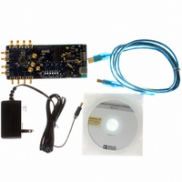
BOARD EVAL FOR AD9516-3 2.0GHZ
Manufacturer
Analog Devices Inc
Specifications of AD9516-3/PCBZ
Main Purpose
Timing, Clock Generator
Embedded
No
Utilized Ic / Part
AD9516-3
Primary Attributes
2 Inputs, 14 Outputs, 2GHz VCO
Secondary Attributes
CMOS, LVDS, LVPECL Output Logic, ADIsimCLK™ Graphical User Interface
Silicon Manufacturer
Analog Devices
Application Sub Type
PLL Clock Synthesizer
Kit Application Type
Clock & Timing
Silicon Core Number
AD9516-0, AD9516-1, AD9516-2
Silicon Family Name
AD9516-X
Rohs Compliant
Yes
Lead Free Status / RoHS Status
Lead free / RoHS Compliant


REGISTER MAP DESCRIPTIONS
Table 53 through Table 62 provide a detailed description of each of the control register functions. The registers are listed by hexadecimal
address. A range of bits (for example, from Bit 5 through Bit 2) is indicated using a colon and brackets, as follows: [5:2].
Table 53. Serial Port Configuration
Reg.
Addr
(Hex)
0x000
0x003
0x004
Bits
[7:4]
3
2
1
0
[7:0]
0
Name
Mirrored, Bits[3:0]
Long instruction
Soft reset
LSB first
SDO active
Part ID (read only)
Read back active registers
Description
Bits[7:4] should always mirror Bits[3:0] so that it does not matter whether the part
is in MSB or LSB first mode (see Bit 1, Register 0x000). The user should set the bits as follows:
Bit 7 = Bit 0.
Bit 6 = Bit 1.
Bit 5 = Bit 2.
Bit 4 = Bit 3.
Short/long instruction mode. This part uses long instruction mode only, so this bit should
always be set to 1.
0: 8-bit instruction (short).
1: 16-bit instruction (long) (default).
Soft reset.
1: soft reset; restores default values to internal registers. Not self-clearing. Must be cleared to
0 to complete reset operation.
MSB or LSB data orientation.
0: data-oriented MSB first; addressing decrements (default).
1: data-oriented LSB first; addressing increments.
Selects unidirectional or bidirectional data transfer mode.
0: SDIO pin used for write and read; SDO set to high impedance; bidirectional mode (default).
1: SDO used for read, SDIO used for write; unidirectional mode.
Uniquely identifies the dash version (-0 through -4) of the AD9516.
AD9516-0: 0x01.
AD9516-1: 0x41.
AD9516-2: 0x81.
AD9516-3: 0x43.
AD9516-4: 0xC3.
Selects register bank used for a readback.
0: reads back buffer registers (default).
1: reads back active registers.
Rev. A | Page 59 of 80
AD9516-3
Related parts for AD9516-3/PCBZ
Image
Part Number
Description
Manufacturer
Datasheet
Request
R

Part Number:
Description:
IC CLOCK PLL/VCO 2GHZ 64LFCSP
Manufacturer:
Analog Devices Inc
Datasheet:
Part Number:
Description:
IC CLOCK GEN 2.8GHZ VCO 64-LFCSP
Manufacturer:
Analog Devices Inc
Datasheet:
Part Number:
Description:
IC,Fourteen Distributed-Output Clock Driver,LLCC,64PIN,PLASTIC
Manufacturer:
Analog Devices Inc
Datasheet:
Part Number:
Description:
IC,Ten Distributed-Output Clock Driver,LLCC,64PIN,PLASTIC
Manufacturer:
Analog Devices Inc
Datasheet:
Part Number:
Description:
IC,Ten Distributed-Output Clock Driver,LLCC,64PIN,PLASTIC
Manufacturer:
Analog Devices Inc
Datasheet:
Part Number:
Description:
Clock IC With 1.8GHz On-chip VCO
Manufacturer:
Analog Devices Inc
Datasheet:

Part Number:
Description:
BOARD EVAL FOR AD9516-2 2.2GHZ
Manufacturer:
Analog Devices Inc
Datasheet:

Part Number:
Description:
Clock IC With 2.5GHz On-chip VCO EB
Manufacturer:
Analog Devices Inc
Datasheet:
Part Number:
Description:
IC CLOCK GEN 2.8GHZ VCO 64-LFCSP
Manufacturer:
Analog Devices Inc
Datasheet:
Part Number:
Description:
IC,Ten Distributed-Output Clock Driver,LLCC,64PIN,PLASTIC
Manufacturer:
Analog Devices Inc
Datasheet:
Part Number:
Description:
IC,Fourteen Distributed-Output Clock Driver,LLCC,64PIN,PLASTIC
Manufacturer:
Analog Devices Inc
Datasheet:
Part Number:
Description:
IC,Ten Distributed-Output Clock Driver,LLCC,64PIN,PLASTIC
Manufacturer:
Analog Devices Inc
Datasheet:
Part Number:
Description:
Clock IC With 1.8GHz On-chip VCO
Manufacturer:
Analog Devices Inc
Datasheet:
Part Number:
Description:
10/14 Chan Clock IC W/PLL-no VCO
Manufacturer:
Analog Devices Inc
Datasheet:
Part Number:
Description:
10/14 Chan Clock IC W/PLL-no VCO
Manufacturer:
Analog Devices Inc
Datasheet: