STEVAL-SCM001V1 STMicroelectronics, STEVAL-SCM001V1 Datasheet - Page 24
STEVAL-SCM001V1
Manufacturer Part Number
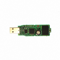
STEVAL-SCM001V1
Description
KIT DEMO DONGLE RTC M41T62/ST7
Manufacturer
STMicroelectronics
Datasheets
1.M41T62Q6F.pdf
(43 pages)
2.STEVAL-SCM001V1.pdf
(4 pages)
3.STEVAL-SCM001V1.pdf
(4 pages)
Specifications of STEVAL-SCM001V1
Design Resources
STEVAL-SCM001V1 Gerber Files STEVAL-SCM001V1/RTC Schematic
Main Purpose
Timing, ARM7 based RTC USB Dongle
Embedded
Yes, MCU, 8-Bit
Utilized Ic / Part
M41T62, ST72F651
Primary Attributes
RTC (Real-Time Clock) and Mass Storage Capabilities
Secondary Attributes
Graphical User Interface, USB Interface
Silicon Manufacturer
ST Micro
Silicon Core Number
M41T62 And ST72651AR6
Kit Application Type
Clock & Timing
Application Sub Type
RTC Dongle
Kit Contents
Board CD Docs
Lead Free Status / RoHS Status
Lead free / RoHS Compliant
Other names
497-5684
Available stocks
Company
Part Number
Manufacturer
Quantity
Price
Company:

Part Number:
STEVAL-SCM001V1
Manufacturer:
STMicroelectronics
Quantity:
135


Clock operation
3.2
24/43
Calibrating the clock
The M41T6x real-time clock is driven by a quartz controlled oscillator with a nominal
frequency of 32,768 Hz. This provides the time-base for the RTC. The accuracy of the clock
depends on the frequency accuracy of the crystal, and the match between the capacitive
load of the oscillator circuit and the capacitive load for which the crystal was trimmed. The
M41T6x oscillator is designed for use with a 6 - 7 pF crystal load capacitance. When the
calibration circuit is properly employed, accuracy improves to better than ±2 ppm at 25 °C.
The oscillation rate of crystals changes with temperature (see
Therefore, the M41T6x design employs periodic counter correction. The calibration circuit
adds or subtracts counts from the oscillator divider circuit at the divide by 256 stage, as
shown in
negative calibration) or split (added, positive calibration) depends upon the value loaded into
the five calibration bits found in the calibration register. Adding counts speeds the clock up,
subtracting counts slows the clock down.
The calibration bits occupy the five lower order bits (D4-D0) in the calibration register (08h).
These bits can be set to represent any value between 0 and 31 in binary form. Bit D5 is a
sign bit; '1' indicates positive calibration, '0' indicates negative calibration. Calibration occurs
within a 64 minute cycle. The first 62 minutes in the cycle may, once per minute, have one
second either shortened by 128 or lengthened by 256 oscillator cycles. If a binary '1' is
loaded into the register, only the first 2 minutes in the 64 minute cycle will be modified; if a
binary 6 is loaded, the first 12 will be affected, and so on.
Therefore, each calibration step has the effect of adding 512 or subtracting 256 oscillator
cycles for every 125,829,120 actual oscillator cycles, that is +4.068 or –2.034 ppm of
adjustment per calibration step in the calibration register.
Assuming that the oscillator is running at exactly 32,768 Hz, each of the 31 increments in
the calibration byte would represent +10.7 or –5.35 seconds per day which corresponds to a
total range of +5.5 or –2.75 minutes per month (see
Two methods are available for ascertaining how much calibration a given M41T6x may
require:
●
●
Any deviation from 512 Hz indicates the degree and direction of oscillator frequency shift at
the test temperature. For example, a reading of 512.010124 Hz would indicate a +20 ppm
oscillator frequency error, requiring a –10 (XX001010) to be loaded into the calibration byte
for correction. Note that setting or changing the calibration byte does not affect the
frequency test or square wave output frequency.
The first involves setting the clock, letting it run for a month and comparing it to a known
accurate reference and recording deviation over a fixed period of time. Calibration
values, including the number of seconds lost or gained in a given period, can be found
in application note AN934, “TIMEKEEPER
give the end user the ability to calibrate the clock as the environment requires, even if
the final product is packaged in a non-user serviceable enclosure. The designer could
provide a simple utility that accesses the calibration byte.
The second approach is better suited to a manufacturing environment, and involves the
use of either the SQW pin (M41T62/63/64) or the IRQ/FT/OUT pin (M41T65). The
SQW pin will toggle at 512 Hz when RS3 = '0,' RS2 = '1,' RS1 = '1,' RS0 = '0,' SQ
WE = '1,' and ST = '0.' Alternatively, for the M41T65, the IRQ/FT/OUT pin will toggle at
512 Hz when FT and OUT bits = '1' and ST = '0.'
Figure 22 on page
25. The number of times pulses which are blanked (subtracted,
Doc ID 10397 Rev 15
®
calibration.” This allows the designer to
Figure 22 on page
Figure 21 on page
25).
M41T62/63/64/65
25).
Related parts for STEVAL-SCM001V1
Image
Part Number
Description
Manufacturer
Datasheet
Request
R

Part Number:
Description:
DEMO BOARD FOR SINGLE OP-AMPS
Manufacturer:
STMicroelectronics
Datasheet:

Part Number:
Description:
KIT EVAL USB/RS232 ST7
Manufacturer:
STMicroelectronics
Datasheet:

Part Number:
Description:
BOARD EVAL HDMI $ VIDEO SWITCH
Manufacturer:
STMicroelectronics
Datasheet:

Part Number:
Description:
BOARD DEMO MEMS LPR430AL
Manufacturer:
STMicroelectronics
Datasheet:

Part Number:
Description:
BOARD EVALUATION FOR LPR550AL
Manufacturer:
STMicroelectronics
Datasheet:

Part Number:
Description:
EVAL BOARD A/D TS4657
Manufacturer:
STMicroelectronics
Datasheet:

Part Number:
Description:
BOARD & REF DESIGN
Manufacturer:
STMicroelectronics
Datasheet:

Part Number:
Description:
BOARD EVAL S-TOUCH STM32
Manufacturer:
STMicroelectronics
Datasheet:

Part Number:
Description:
BOARD ADAPTER LPR403AL DIL24
Manufacturer:
STMicroelectronics
Datasheet:

Part Number:
Description:
BOARD DEMO LPR4150AL GYROSCOPE
Manufacturer:
STMicroelectronics
Datasheet:
Part Number:
Description:
STMicroelectronics [RIPPLE-CARRY BINARY COUNTER/DIVIDERS]
Manufacturer:
STMicroelectronics
Datasheet:
Part Number:
Description:
STMicroelectronics [LIQUID-CRYSTAL DISPLAY DRIVERS]
Manufacturer:
STMicroelectronics
Datasheet:

Part Number:
Description:
BOARD EVAL FOR MEMS SENSORS
Manufacturer:
STMicroelectronics
Datasheet: