STEVAL-SCM001V1 STMicroelectronics, STEVAL-SCM001V1 Datasheet - Page 26
STEVAL-SCM001V1
Manufacturer Part Number
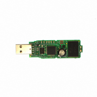
STEVAL-SCM001V1
Description
KIT DEMO DONGLE RTC M41T62/ST7
Manufacturer
STMicroelectronics
Datasheets
1.M41T62Q6F.pdf
(43 pages)
2.STEVAL-SCM001V1.pdf
(4 pages)
3.STEVAL-SCM001V1.pdf
(4 pages)
Specifications of STEVAL-SCM001V1
Design Resources
STEVAL-SCM001V1 Gerber Files STEVAL-SCM001V1/RTC Schematic
Main Purpose
Timing, ARM7 based RTC USB Dongle
Embedded
Yes, MCU, 8-Bit
Utilized Ic / Part
M41T62, ST72F651
Primary Attributes
RTC (Real-Time Clock) and Mass Storage Capabilities
Secondary Attributes
Graphical User Interface, USB Interface
Silicon Manufacturer
ST Micro
Silicon Core Number
M41T62 And ST72651AR6
Kit Application Type
Clock & Timing
Application Sub Type
RTC Dongle
Kit Contents
Board CD Docs
Lead Free Status / RoHS Status
Lead free / RoHS Compliant
Other names
497-5684
Available stocks
Company
Part Number
Manufacturer
Quantity
Price
Company:

Part Number:
STEVAL-SCM001V1
Manufacturer:
STMicroelectronics
Quantity:
135


Clock operation
3.3
Note:
26/43
Setting alarm clock registers
Address locations 0Ah-0Eh contain the alarm settings. The alarm can be configured to go
off at a prescribed time on a specific month, date, hour, minute, or second, or repeat every
year, month, day, hour, minute, or second. Bits RPT5–RPT1 put the alarm in the repeat
mode of operation.
in the table default to the once per second mode to quickly alert the user of an incorrect
alarm setting.
When the clock information matches the alarm clock settings based on the match criteria
defined by RPT5–RPT1, the AF (alarm flag) is set. If AFE (alarm flag enable) is also set
(M41T62/65), the alarm condition activates the IRQ/OUT or IRQ/FT/OUT pin. To disable the
alarm, write '0' to the alarm date register and to RPT5–RPT1.
If the address pointer is allowed to increment to the flag register address, an alarm condition
will not cause the interrupt/flag to occur until the address pointer is moved to a different
address. It should also be noted that if the last address written is the “Alarm Seconds,” the
address pointer will increment to the flag address, causing this situation to occur.
The IRQ output is cleared by a READ to the flags register as shown in
page
alarm flag has been reset to '0.'
Figure 23. Alarm interrupt reset waveform
Table 7.
Register address
ALARM FLAG BIT (AF)
IRQ/OUT or
IRQ/FT/OUT
RPT5
1
1
1
1
1
0
26. A subsequent READ of the flags register is necessary to see that the value of the
Alarm repeat modes
RPT4
1
1
1
1
0
0
0Eh
Table 7 on page 26
RPT3
1
1
1
0
0
0
Doc ID 10397 Rev 15
RPT2
shows the possible configurations. Codes not listed
1
1
0
0
0
0
0Fh
RPT1
1
0
0
0
0
0
Once per second
Once per minute
Once per month
Alarm setting
Once per hour
Once per year
Once per day
Figure 23 on
M41T62/63/64/65
HIGH-Z
00h
AI08898
Related parts for STEVAL-SCM001V1
Image
Part Number
Description
Manufacturer
Datasheet
Request
R

Part Number:
Description:
DEMO BOARD FOR SINGLE OP-AMPS
Manufacturer:
STMicroelectronics
Datasheet:

Part Number:
Description:
KIT EVAL USB/RS232 ST7
Manufacturer:
STMicroelectronics
Datasheet:

Part Number:
Description:
BOARD EVAL HDMI $ VIDEO SWITCH
Manufacturer:
STMicroelectronics
Datasheet:

Part Number:
Description:
BOARD DEMO MEMS LPR430AL
Manufacturer:
STMicroelectronics
Datasheet:

Part Number:
Description:
BOARD EVALUATION FOR LPR550AL
Manufacturer:
STMicroelectronics
Datasheet:

Part Number:
Description:
EVAL BOARD A/D TS4657
Manufacturer:
STMicroelectronics
Datasheet:

Part Number:
Description:
BOARD & REF DESIGN
Manufacturer:
STMicroelectronics
Datasheet:

Part Number:
Description:
BOARD EVAL S-TOUCH STM32
Manufacturer:
STMicroelectronics
Datasheet:

Part Number:
Description:
BOARD ADAPTER LPR403AL DIL24
Manufacturer:
STMicroelectronics
Datasheet:

Part Number:
Description:
BOARD DEMO LPR4150AL GYROSCOPE
Manufacturer:
STMicroelectronics
Datasheet:
Part Number:
Description:
STMicroelectronics [RIPPLE-CARRY BINARY COUNTER/DIVIDERS]
Manufacturer:
STMicroelectronics
Datasheet:
Part Number:
Description:
STMicroelectronics [LIQUID-CRYSTAL DISPLAY DRIVERS]
Manufacturer:
STMicroelectronics
Datasheet:

Part Number:
Description:
BOARD EVAL FOR MEMS SENSORS
Manufacturer:
STMicroelectronics
Datasheet: