STM8/128-MCKIT STMicroelectronics, STM8/128-MCKIT Datasheet - Page 10
STM8/128-MCKIT
Manufacturer Part Number
STM8/128-MCKIT
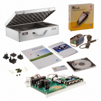
Description
EVAL KIT MOTOR CONTROL STM8S
Manufacturer
STMicroelectronics
Series
STM8Sr
Datasheets
1.STM8128-MCKIT.pdf
(22 pages)
2.STM8128-MCKIT.pdf
(4 pages)
3.STM8128-MCKIT.pdf
(41 pages)
Specifications of STM8/128-MCKIT
Main Purpose
Power Management, Motor Control
Embedded
Yes, MCU, 8-Bit
Utilized Ic / Part
STM8S2xx
Primary Attributes
Brushless DC (BLDC) & AC Induction (ACIM) Motors
Secondary Attributes
Joystick & LCD User Interface
Processor To Be Evaluated
STM8S
Data Bus Width
8 bit
Operating Supply Voltage
2.95 V to 5.5 V
Silicon Manufacturer
ST Micro
Silicon Core Number
STM8
Features
Motor Control Applications, The Inverter Is Driven Using The Space Vector PWM Modulation Technique
Lead Free Status / RoHS Status
Not applicable / Not applicable
Other names
497-10032


Hardware layout and configuration
1.9
10/41
selected by setting jumpers JP11 and JP12. The LIN1 and LIN2 transceivers are powered
by an external voltage from 6V to 26V connected to pin 9 of the LIN DB9 connector.
Table 6.
Motor control
The STM8/128-EVAL evaluation board supports inductor motor control via a 34-pin
connector CN10, which provides all required control and feedback signals to and from the
motor power-driving board. Available signals on this connector include emergency stop,
motor speed, 3-phase motor current, bus voltage, heatsink temperature coming from the
motor driving board and 6 channels of PWM control signals going to the motor driving
circuit.
Either PFC_PWM or Dissipative_Brake signal can be enabled by setting jumper JP13.
Table 7.
JP11
JP12
JP13
Jumper/resis
Jumper
tor
LIN related jumpers
Motor control related configuration
LIN1 operates in master mode when JP11 is set as shown:
This is the default setting.
LIN1 operates in slave mode when JP11 is set as shown:
LIN2 operates in master mode when JP12 is set as shown:
LIN2 operates in slave mode when JP12 is set as shown:
This is the default setting.
PFC_PWM signal is enabled and connected to PD0 when JP13 is
set as shown:
This is the default setting.
Dissipative_Brake signal is enabled and connected to PD0 when
JP13 is set as shown:
Description
Description
1 2 3
1 2 3
1 2 3
1 2 3
1 2 3
1 2 3
UM0482
Related parts for STM8/128-MCKIT
Image
Part Number
Description
Manufacturer
Datasheet
Request
R

Part Number:
Description:
KIT STARTER FOR STM8S207/8 SER
Manufacturer:
STMicroelectronics
Datasheet:

Part Number:
Description:
BOARD DAUGHTER FOR STM8S207/8
Manufacturer:
STMicroelectronics
Datasheet:

Part Number:
Description:
EVAL KIT TOUCH SENSING STM8S
Manufacturer:
STMicroelectronics
Datasheet:

Part Number:
Description:
BOARD EVAL FOR STM8S
Manufacturer:
STMicroelectronics
Datasheet:
Part Number:
Description:
STM8 Series 8-bit 8 KB Flash 1 KB RAM 16 MHz Microcontroller - TSSOP-20
Manufacturer:
STMicroelectronics
Datasheet:
Part Number:
Description:
STMicroelectronics [RIPPLE-CARRY BINARY COUNTER/DIVIDERS]
Manufacturer:
STMicroelectronics
Datasheet:
Part Number:
Description:
STMicroelectronics [LIQUID-CRYSTAL DISPLAY DRIVERS]
Manufacturer:
STMicroelectronics
Datasheet:

Part Number:
Description:
BOARD EVAL FOR MEMS SENSORS
Manufacturer:
STMicroelectronics
Datasheet:
Part Number:
Description:
NPN TRANSISTOR POWER MODULE
Manufacturer:
STMicroelectronics
Datasheet:
Part Number:
Description:
TURBOSWITCH ULTRA-FAST HIGH VOLTAGE DIODE
Manufacturer:
STMicroelectronics
Datasheet:
Part Number:
Description:
Manufacturer:
STMicroelectronics
Datasheet:
Part Number:
Description:
DIODE / SCR MODULE
Manufacturer:
STMicroelectronics
Datasheet: