STM8/128-MCKIT STMicroelectronics, STM8/128-MCKIT Datasheet - Page 8
STM8/128-MCKIT
Manufacturer Part Number
STM8/128-MCKIT
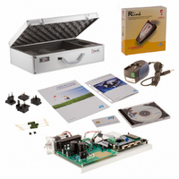
Description
EVAL KIT MOTOR CONTROL STM8S
Manufacturer
STMicroelectronics
Series
STM8Sr
Datasheets
1.STM8128-MCKIT.pdf
(22 pages)
2.STM8128-MCKIT.pdf
(4 pages)
3.STM8128-MCKIT.pdf
(41 pages)
Specifications of STM8/128-MCKIT
Main Purpose
Power Management, Motor Control
Embedded
Yes, MCU, 8-Bit
Utilized Ic / Part
STM8S2xx
Primary Attributes
Brushless DC (BLDC) & AC Induction (ACIM) Motors
Secondary Attributes
Joystick & LCD User Interface
Processor To Be Evaluated
STM8S
Data Bus Width
8 bit
Operating Supply Voltage
2.95 V to 5.5 V
Silicon Manufacturer
ST Micro
Silicon Core Number
STM8
Features
Motor Control Applications, The Inverter Is Driven Using The Space Vector PWM Modulation Technique
Lead Free Status / RoHS Status
Not applicable / Not applicable
Other names
497-10032


Hardware layout and configuration
1.3
1.4
8/41
Reset source
The reset signal of STM8/128-EVAL evaluation board is low active and the reset sources
include:
●
●
●
The reset pin PA0 of STM8S2XX is connected either to Reset button B1 or to GND by
setting the jumper JP1 as described in
Table 2.
Audio
The STM8/128-EVAL evaluation board supports both audio recording and playback. This
can be disabled or enabled by setting the jumpers JP4 and JP5. Audio volume can be
adjusted using the potentiometer RV2, while the microphone amplifier gain can be adjusted
using potentiometer RV3.
The beeper function pin PD4 is connected to the speaker via the JP14 jumper which can be
used to select the source, beeper or PWM output from STM8S2xx.
Table 3.
JP1
JP4
JP5
JP14
Jumper
Jumper
Reset button B1
Debugging Tools from connector CN4
Daughter board from CN5
Reset related jumpers
Audio related jumpers
PA0 is connected to GND when JP1 is set as shown. It is used to
maintain the reset pin at low level while STice is connected to the
board.
PA0 is connected to Reset button when JP1 is set as shown.
This is the default setting.
The audio power amplifier TS4871 is forced into standby mode when JP4 is not
fitted.
Default setting: fitted
The microphone pre-amplifier MAX4061 is forced into shutdown mode when JP5 is
fitted.
Default setting: not fitted
1 2 3
1 2 3
Either beeper or PWM output can be selected as a source of
speaker by setting the jumper JP14. The beeper is connected to
speaker when JP14 is set as shown opposite.
The PWM output is connected to speaker when JP14 is set as
shown opposite.
This is the default setting.
Table
2.
Description
Description
1 2 3
1 2 3
UM0482
Related parts for STM8/128-MCKIT
Image
Part Number
Description
Manufacturer
Datasheet
Request
R

Part Number:
Description:
KIT STARTER FOR STM8S207/8 SER
Manufacturer:
STMicroelectronics
Datasheet:

Part Number:
Description:
BOARD DAUGHTER FOR STM8S207/8
Manufacturer:
STMicroelectronics
Datasheet:

Part Number:
Description:
EVAL KIT TOUCH SENSING STM8S
Manufacturer:
STMicroelectronics
Datasheet:

Part Number:
Description:
BOARD EVAL FOR STM8S
Manufacturer:
STMicroelectronics
Datasheet:
Part Number:
Description:
STM8 Series 8-bit 8 KB Flash 1 KB RAM 16 MHz Microcontroller - TSSOP-20
Manufacturer:
STMicroelectronics
Datasheet:
Part Number:
Description:
STMicroelectronics [RIPPLE-CARRY BINARY COUNTER/DIVIDERS]
Manufacturer:
STMicroelectronics
Datasheet:
Part Number:
Description:
STMicroelectronics [LIQUID-CRYSTAL DISPLAY DRIVERS]
Manufacturer:
STMicroelectronics
Datasheet:

Part Number:
Description:
BOARD EVAL FOR MEMS SENSORS
Manufacturer:
STMicroelectronics
Datasheet:
Part Number:
Description:
NPN TRANSISTOR POWER MODULE
Manufacturer:
STMicroelectronics
Datasheet:
Part Number:
Description:
TURBOSWITCH ULTRA-FAST HIGH VOLTAGE DIODE
Manufacturer:
STMicroelectronics
Datasheet:
Part Number:
Description:
Manufacturer:
STMicroelectronics
Datasheet:
Part Number:
Description:
DIODE / SCR MODULE
Manufacturer:
STMicroelectronics
Datasheet: