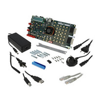
DK-SI-4S100G2N Altera, DK-SI-4S100G2N Datasheet - Page 21

DK-SI-4S100G2N
Manufacturer Part Number
DK-SI-4S100G2N
Description
KIT DEV STRATIX IV TRANSCEIVER
Manufacturer
Altera
Series
Stratix® IVr
Datasheet
1.DK-SI-4S100G2N.pdf
(28 pages)
Specifications of DK-SI-4S100G2N
Main Purpose
*
Embedded
*
Utilized Ic / Part
EP4S100G2F40C2ES1
Primary Attributes
*
Secondary Attributes
*
Silicon Manufacturer
Altera
Core Architecture
FPGA
Core Sub-architecture
Stratix
Silicon Core Number
EP4S
Silicon Family Name
Stratix IV GT
Rohs Compliant
Yes
Lead Free Status / RoHS Status
Lead free / RoHS Compliant
Other names
544-2603
Overview
Parallel Flash Loader
Board Update Portal CFI Flash Memory Map
© December 2009 Altera Corporation
f
f
There is a Common Flash Interface (CFI) type flash memory device on the
Stratix IV GT transceiver signal integrity board. When you first receive the kit, the
CFI flash device arrives programmed with a default factory FPGA configuration for
running the Board Update Portal example design and a default user configuration for
running the primary transceiver signal integrity demonstration. There are several
other factory software files written to the CFI flash device to support the running of
the Board Update Portal. These software files were created using the Nios II EDS just
as the hardware design was created using the Quartus II Design application.
For more information about Altera development tools, refer to
www.altera.com/products/software/sfw-index.jsp.
The development kit features a MAX II configuration design in the <install
dir>\kits\stratixIVGT_4s100g2_si\examples\maxII_epm1270_si directory that
includes a PFL megafunction. The Parallel Flash Loader (PFL) on the MAX II device is
used to configure from CFI flash when the RESET SW8 is pressed or the board is
powered up.
For more information about the PFL megafunction, refer to
Flash Loader with the Quartus II
Table A–1
PC48F4400P0VB00 CFI flash device. For the Board Update Portal to run correctly and
update designs in the user memory, this memory map must not be altered.
Table A–1. Byte Address Flash Memory Map (Part 1 of 2)
Unused
Unused
Unused
Unused
User software
Factory software
zipfs (html, web content)
User hardware
Factory hardware
PFL option bits
Block Description
shows the default memory contents of the 512-Mb (64-MB) Intel
Transceiver Signal Integrity Development Kit, Stratix IV GT Edition User Guide
Software.
A. Programming the Flash Device
24,320 KB
12,288 KB
12,288 KB
8,192 KB
8,192 KB
Size
32 KB
32 KB
32 KB
32 KB
32 KB
0x02820000 - 0x03FDFFFF
0x02020000 - 0x0281FFFF
0x01820000 - 0x0201FFFF
0x00C20000 - 0x0181FFFF
0x00020000 - 0x00C1FFFF
0x00018000 - 0x0001FFFF
0x03FE8000 - 0x03FEFFFF
0x03FE0000 - 0x03FE7FFF
0x03FF8000 - 0x03FFFFFF
0x03FF0000 - 0x03FF7FFF
Address Range
AN 386: Using the Parallel


