VSUPEV2 Microchip Technology, VSUPEV2 Datasheet - Page 20
VSUPEV2
Manufacturer Part Number
VSUPEV2
Description
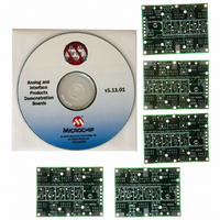
BOARD EVAL FOR MCP4022,4023,4024
Manufacturer
Microchip Technology
Specifications of VSUPEV2
Main Purpose
Power Management, Power Supply Supervisor/Tracker/Sequencer
Embedded
No
Utilized Ic / Part
SOT-23-5, SOT-23-6 Package
Primary Attributes
Voltage Detector & Supervisor
Secondary Attributes
5 Boards & 3 IC's Included
Processor To Be Evaluated
SOT23-5/6
Lead Free Status / RoHS Status
Lead free / RoHS Compliant
Lead Free Status / RoHS Status
Lead free / RoHS Compliant, Lead free / RoHS Compliant


Voltage Supervisor SOT-23-5/6 Evaluation Board User’s Guide
FIGURE 2-3:
FIGURE 2-4:
DS51527B-page 16
V
SS
3
1
2
Option A
2.4.3
There are four SOT-23-6 and one SOT-23-5 pinout options that the Voltage Supervisor
SOT-23-5/6 Evaluation Board PCB supports. Figure 2-3 shows these four pinouts.
Figure 2-4 shows the single SOT-23-5 pinout option. Some devices may use different
nomenclature for the pin names, such as GND instead of V
RESET (or RESET) or RST instead of V
Other Microchip analog devices may be used with this PCB if the power and ground
pins match one of these four options. Appendix C. “Microchip SOT-23-5/6 Device
Compatibility” discusses other Microchip analog devices that may be used with this
PCB.
SOT-23-6 (and SOT-23-5) Pinout Options.
SOT-23-5 Pinout Option.
2.4.4
The footprints for these components are present to allow maximum flexibility in the use
of this PCB to evaluate a wide range of SOT-23-3 devices. The purpose of these com-
ponents may vary depending on the device under evaluation and how it is to be used
in the desired circuit. Please refer to the device data sheet for the recommended
components that should be used when evaluating that device.
2.4.5
The footprints for these components are present to allow maximum flexibility in the use
of this PCB to evaluate a wide range of SOT-23-5 and SOT-23-6 devices. The purpose
of these components may vary depending on the device under evaluation and how it is
to be used in the desired circuit. Please refer to the device data sheet for the
recommended components that should be used when evaluating that device.
2.4.6
The Baseline Flash Microcontroller Programmer (BFMP) interface allows a
PIC10F2XX device that is populated in the SOT-23-6 version E footprint to be
programmed with programmers that support this interface, such as the BFMP
programmer (part number PG164101).
6
5
4
V
DD
SOT-23-6 and SOT-23-5 Footprints
Passive Components (R1x, R2x, R3x, C5x, R1, R2, C1, C2, C3,
C4 and C6)
Switches (S1 and S2)
BFMP Interface (Header J1)
V
DD
1
3
2
Option B
V
V
DD
SS
6
5
4
V
3
1
2
SS
Option D
V
V
DD
SS
5
4
OUT
Option C
3
1
2
.
6
5
4
V
SS
© 2006 Microchip Technology Inc.
SS
, V
1
3
2
IN
Option E
instead of V
6
5
4
V
DD
DD
and
Related parts for VSUPEV2
Image
Part Number
Description
Manufacturer
Datasheet
Request
R

Part Number:
Description:
Manufacturer:
Microchip Technology Inc.
Datasheet:
Part Number:
Description:
Manufacturer:
Microchip Technology Inc.
Datasheet:
Part Number:
Description:
Manufacturer:
Microchip Technology Inc.
Datasheet:
Part Number:
Description:
Manufacturer:
Microchip Technology Inc.
Datasheet:
Part Number:
Description:
Manufacturer:
Microchip Technology Inc.
Datasheet:
Part Number:
Description:
Manufacturer:
Microchip Technology Inc.
Datasheet:
Part Number:
Description:
Manufacturer:
Microchip Technology Inc.
Datasheet:
Part Number:
Description:
Manufacturer:
Microchip Technology Inc.
Datasheet: