VSUPEV2 Microchip Technology, VSUPEV2 Datasheet - Page 25
VSUPEV2
Manufacturer Part Number
VSUPEV2
Description
BOARD EVAL FOR MCP4022,4023,4024
Manufacturer
Microchip Technology
Specifications of VSUPEV2
Main Purpose
Power Management, Power Supply Supervisor/Tracker/Sequencer
Embedded
No
Utilized Ic / Part
SOT-23-5, SOT-23-6 Package
Primary Attributes
Voltage Detector & Supervisor
Secondary Attributes
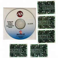
5 Boards & 3 IC's Included
Processor To Be Evaluated
SOT23-5/6
Lead Free Status / RoHS Status
Lead free / RoHS Compliant
Lead Free Status / RoHS Status
Lead free / RoHS Compliant, Lead free / RoHS Compliant


2.6
© 2006 Microchip Technology Inc.
DIGITAL POTENTIOMETER CIRCUIT
The Voltage Supervisor SOT-23-5/6 Evaluation Board can be utilized to demonstrate
and test Microchip’s SOT-23-5 and SOT-23-6 nonvolatile digital potentiometers. This is
accomplished by populating the PCB with the desired MCP401X or MCP402X device,
a PIC10F2XX microcontroller, two momentary switches and a few resistors.
The code supplied for this evaluation board may be easily modified to demonstrate
operation of the Voltage Supervisor SOT-23-5/6 Evaluation Board.
Section 2.3 and Section 2.4 of the MCP401X/2X Digital Potentiometer Evaluation
Board User’s Guide (DS51546) discuss the MCP402XEV firmware. This firmware can
easily be modified to demonstrate using the Voltage Supervisor SOT-23-5/6 Evaluation
Board.
Figure 2-9 illustrates an example circuit. This circuit uses the MCP4023 and
PIC10F200 devices with all the components installed. The PCB silk-screen indicates
the VDD and VSS pads. The remaining PCB pads will be referred to by their footprint
option/pin number combination. These combinations are C3, C4, C5 and C6.
The PIC10F2XX will need to be programmed to make the system work. The
PIC10F2XX device can be programmed via the Baseline Flash Microcontroller
Programmer (BFMP) header (J1). The program (firmware) configures the GP1 and
GP2 pins to be outputs (driving high) and the GP0 and GP3 pins to be inputs. The GP1
and GP2 pins are individually polled to determine if either switch S1/D (down) and S2/U
(up) are depressed.
If the nonvolatile MCP402X device is used, the digital potentiometer setting can be
stored in nonvolatile memory, power can be cycled and the digital potentiometer will be
at the last saved setting for the volatile versions of the device. The wiper will go to its
default setting when power is cycled.
Note:
Note:
Microchip Technology Inc. offers a built-up evaluation board for the
MCP402X Digital Potentiometer (MCP402XEV). Additional information
regarding this evaluation board may be found on the CD-ROM directory:
CD-ROM:\00066 - MCP402X Digital Potentiometer Evalua-
tion Board. Within this directory, you will find the user’s guide for this
evaluation board, the PIC10F200 program (firmware) and assembled HEX
file (00066_MCP402XEV.hex).
The PIC10F2XX program (firmware) must take care in the timing require-
ments of the GP1 and GP2 pins, due to the multiplexing of the PIC10F2XX
GP1 pin with the MCP4023 U/D pin and Switch S1, and the multiplexing of
the PIC10F2XX GP2 pin with the MCP4023 CS pin and switch S2.
DS51527B-page 21
Related parts for VSUPEV2
Image
Part Number
Description
Manufacturer
Datasheet
Request
R

Part Number:
Description:
Manufacturer:
Microchip Technology Inc.
Datasheet:
Part Number:
Description:
Manufacturer:
Microchip Technology Inc.
Datasheet:
Part Number:
Description:
Manufacturer:
Microchip Technology Inc.
Datasheet:
Part Number:
Description:
Manufacturer:
Microchip Technology Inc.
Datasheet:
Part Number:
Description:
Manufacturer:
Microchip Technology Inc.
Datasheet:
Part Number:
Description:
Manufacturer:
Microchip Technology Inc.
Datasheet:
Part Number:
Description:
Manufacturer:
Microchip Technology Inc.
Datasheet:
Part Number:
Description:
Manufacturer:
Microchip Technology Inc.
Datasheet: