MXSIGDM Microchip Technology, MXSIGDM Datasheet - Page 13
MXSIGDM
Manufacturer Part Number
MXSIGDM
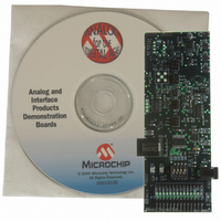
Description
BOARD DEMO PICTAIL MIXED SIGNAL
Manufacturer
Microchip Technology
Series
PICtail™r
Datasheet
1.MXSIGDM.pdf
(54 pages)
Specifications of MXSIGDM
Main Purpose
Mixed Signal for MCU: ADC, DAC,
Embedded
Yes, MCU, 8-Bit
Utilized Ic / Part
TX132x,MCP330x,320x,494x,3221,3201,1525,1541
Primary Attributes
3 ADCs, 3 DACs, 2 Voltage References, 5V LDO
Secondary Attributes
DIP Switches, 2 LEDs, PIC16F767
Processor To Be Evaluated
TC132x, MCP330x, MCP320x, MCP492x, MCP3221, MCP3021, MCP15x
Interface Type
I2C, SPI
Lead Free Status / RoHS Status
Contains lead / RoHS non-compliant
Lead Free Status / RoHS Status
Lead free / RoHS Compliant, Contains lead / RoHS non-compliant


2.1
2.2
2.3
2004 Microchip Technology Inc.
INTRODUCTION
FEATURES
GETTING STARTED
Chapter 2. Installation and Operation
The Mixed Signal PICtail™ Demo Board demonstrates several Microchip analog
products in a signal chain configuration. The product families demonstrated include
DACs, ADCs, V
precision analog products for specific applications can be challenging due to noise
sources related to the PCB layout and not the silicon under evaluation. The Mixed Signal
PICtail™ Demo Board provides the necessary hardware and firmware to exercise each
of these devices in real-world applications. Users can quickly modify the existing
hardware and firmware to validate functionality for their specific system needs.
The Mixed Signal PICtail™ Demo Board has the following features:
• Printed Circuit Board (PCB) is a 4-layer board designed to minimize external
• A 28-pin PICmicro (PIC16F767) microcontroller footprint is provided to permit
• The 14-pin header is designed to seamlessly interface to the PICkit™ 1 Flash
• Firmware demonstrating DTMF generation on the MCP492X/482X DAC is
• Firmware demonstrating a precision sine-wave generation on the TC132X DAC is
• Firmware to configure and read the MCP330X/320X SAR ADCs is included
• Two precision voltage references (V
• Flexible amplifier circuit layout supports a dual op amp in multiple configurations
• Four DIP switches allow simple firmware mode selection are supported
• Two indicator LEDs (red and green) are supported
• Can be powered by either the PICkit™ 1 Flash Starter Kit or by an external 9V
The Mixed Signal PICtail™ Demo Board is assembled and tested for evaluation and
demonstration of the MCP492X, MCP482X, TC132X, MCP3551, MCP3302,
MCP3204, MCP1541, MCP1701, PIC16F767 and MCP617 features. Additional
product samples with footprints supported by this board are included. A block diagram
of the demo board is shown in Figure 2-1. Refer to Appendix A. “Schematics and
Layouts” and Appendix B. “Bill-Of-Materials (BOM)” for more detailed circuit
information.
noise
code development. In-Circuit Debugger is supported via the RJ11 connector
Starter Kit
included
included
for either an input signal filter (ADC) or an output signal-conditioning stage for the
DACs
supply
REF
s, LDOs and PICmicro
Mixed Signal PICtail™ Demo
REF
®
s) are supported (can compare noise)
microcontroller devices. Evaluating
Board User’s Guide
DS51523A-page 9
Related parts for MXSIGDM
Image
Part Number
Description
Manufacturer
Datasheet
Request
R

Part Number:
Description:
Manufacturer:
Microchip Technology Inc.
Datasheet:
Part Number:
Description:
Manufacturer:
Microchip Technology Inc.
Datasheet:
Part Number:
Description:
Manufacturer:
Microchip Technology Inc.
Datasheet:
Part Number:
Description:
Manufacturer:
Microchip Technology Inc.
Datasheet:
Part Number:
Description:
Manufacturer:
Microchip Technology Inc.
Datasheet:
Part Number:
Description:
Manufacturer:
Microchip Technology Inc.
Datasheet:
Part Number:
Description:
Manufacturer:
Microchip Technology Inc.
Datasheet:
Part Number:
Description:
Manufacturer:
Microchip Technology Inc.
Datasheet: