MXSIGDM Microchip Technology, MXSIGDM Datasheet - Page 21
MXSIGDM
Manufacturer Part Number
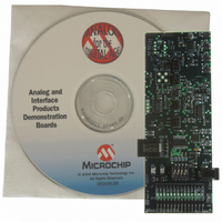
MXSIGDM
Description
BOARD DEMO PICTAIL MIXED SIGNAL
Manufacturer
Microchip Technology
Series
PICtail™r
Datasheet
1.MXSIGDM.pdf
(54 pages)
Specifications of MXSIGDM
Main Purpose
Mixed Signal for MCU: ADC, DAC,
Embedded
Yes, MCU, 8-Bit
Utilized Ic / Part
TX132x,MCP330x,320x,494x,3221,3201,1525,1541
Primary Attributes
3 ADCs, 3 DACs, 2 Voltage References, 5V LDO
Secondary Attributes
DIP Switches, 2 LEDs, PIC16F767
Processor To Be Evaluated
TC132x, MCP330x, MCP320x, MCP492x, MCP3221, MCP3021, MCP15x
Interface Type
I2C, SPI
Lead Free Status / RoHS Status
Contains lead / RoHS non-compliant
Lead Free Status / RoHS Status
Lead free / RoHS Compliant, Contains lead / RoHS non-compliant


2004 Microchip Technology Inc.
2.4.7
Jumper JP5 is located along the right side of the board, just above the 14-pin MCP492X
footprint. JP5 consists of three jumper pins.
JP5 is used to configure the board for the Microchip SPI DAC that gets soldered onto
the board. Refer to Figure 2-2 and Appendix A. “Schematics and Layouts”.
• If the MCP4922 is used, no jumper is required.
• If the MCP4921 is used, a jumper on the right two pins is required.
• If the MCP4822 is used, no jumper is required.
• If the MCP4821 is used, a jumper on the left two pins is required.
2.4.8
The most commonly probed signals are available using the surface-mount test points
located along the sides of the board. These test points are labeled by the silk-screen.
Note that four of these test points are oversized (2x) and are on both sides of the board.
This is convenient for connecting probe ground “alligator” clips. These ground
connections are critical for minimizing probe noise. The MCP3551 22b ADC is sensitive
enough to “see” these noise signals enough to significantly reduce performance. J7 is
a SMA connector to allow a fully-shielded connection from the ADC input (V
your scope. Appendix G. “Scope Probe Noise Captures” illustrates the difference
between a normal probe connection and the SMA connection. As you can see, the
noise is a product of the scope connection, not the op amp buffer or ADC.
2.4.9
When using the PIC16F767 (or any other Flash, 28-pin, PICmicro microcontroller with
compatible footprint) the MPLAB ICD 2 is a low-cost development tool that can be
utilized for code development. The MPLAB ICD 2 has defined a standard connector to
simplify In-Circuit Debugging and In-Circuit Serial Programming (ICSP™) of the
PICmicro microcontroller.
The MPLAB ICD 2 system is particularly advantageous when developing mixed signal
solutions. The MPLAB ICD 2 does not introduce any stray inductance or capacitance
typical of emulators’ adapters, cables and interface boards. The PICmicro
microcontroller can be soldered onto the board just as it would for standard production.
The MPLAB ICD 2 signals remain static during normal operation, therefore adding no
noise to the system while executing code.
This RJ11 connector would not be used if the PICkit™ 1 Flash Starter Kit is used for
development.
Jumper JP5 Selection
Probe Connections
MPLAB ICD 2 Header J4
DS51523A-page 17
OUTD
) to
Related parts for MXSIGDM
Image
Part Number
Description
Manufacturer
Datasheet
Request
R

Part Number:
Description:
Manufacturer:
Microchip Technology Inc.
Datasheet:
Part Number:
Description:
Manufacturer:
Microchip Technology Inc.
Datasheet:
Part Number:
Description:
Manufacturer:
Microchip Technology Inc.
Datasheet:
Part Number:
Description:
Manufacturer:
Microchip Technology Inc.
Datasheet:
Part Number:
Description:
Manufacturer:
Microchip Technology Inc.
Datasheet:
Part Number:
Description:
Manufacturer:
Microchip Technology Inc.
Datasheet:
Part Number:
Description:
Manufacturer:
Microchip Technology Inc.
Datasheet:
Part Number:
Description:
Manufacturer:
Microchip Technology Inc.
Datasheet: