MXSIGDM Microchip Technology, MXSIGDM Datasheet - Page 18
MXSIGDM
Manufacturer Part Number
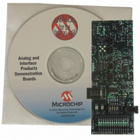
MXSIGDM
Description
BOARD DEMO PICTAIL MIXED SIGNAL
Manufacturer
Microchip Technology
Series
PICtail™r
Datasheet
1.MXSIGDM.pdf
(54 pages)
Specifications of MXSIGDM
Main Purpose
Mixed Signal for MCU: ADC, DAC,
Embedded
Yes, MCU, 8-Bit
Utilized Ic / Part
TX132x,MCP330x,320x,494x,3221,3201,1525,1541
Primary Attributes
3 ADCs, 3 DACs, 2 Voltage References, 5V LDO
Secondary Attributes
DIP Switches, 2 LEDs, PIC16F767
Processor To Be Evaluated
TC132x, MCP330x, MCP320x, MCP492x, MCP3221, MCP3021, MCP15x
Interface Type
I2C, SPI
Lead Free Status / RoHS Status
Contains lead / RoHS non-compliant
Lead Free Status / RoHS Status
Lead free / RoHS Compliant, Contains lead / RoHS non-compliant


DS51523A-page 14
Modes 1XXX primarily utilize TC132X DAC modes:
1. Mode1000: Generate a 100 Hz 32-step sine wave on the TC132X. Analyze
2. Mode1001: Send 000h and FFFh commands to generate a 100 Hz R-R output
3. Mode1010: Send 400h and BFFh commands to generate a 100 Hz output on the
4. Mode1011: DAC = SHDN, PIC = SLEEP. This mode demonstrates the
5. Mode1100: DAC = 200h and Read with PIC16F767 10b ADC, “broadcast on
6. Mode1101: DAC = 200h and Read with MCP3302 13b single-ended, “broadcast
7. Mode1110: Open for user to define their own routine.
8. Mode1111: Open for user to define their own routine.
Refer to Appendix C. “MixedSignal_V100.asm Description” to view source code
and comments.
Refer to Appendix D. “DAC_dtmf.asm Source Code” to view source code and
comments.
Refer to Appendix E. “MixedSignal_16f767i.lkr Source Code” to view the script.
Refer to the p16F767.inc standard include file located in your
“\MPLAB IDE\MCHIP_Tools\” folder.
output on V
Captures” for resulting unfiltered waveform.
on the TC132X. Probe V
TC132X. Probe V
low-power nature of the DAC, the PICmicro microcontroller, the op amp and the
LDO. A power cycle is required after the mode switch is changed to exit this
mode.
USART”. A
which, along with the MCP3551 USB evaluation board, provides a “canned”
analysis solution.
on USART”. A
which, along with the MCP3551 USB evaluation board, provides a “canned”
analysis solution.
IN_C
OUTC
IN_C
can be analyzed using Microchip’s Data View analysis tool,
. See Appendix H. “Sine Wave and Filtered DTMF Scope
OUTC
can be analyzed using Microchip’s Data View analysis tool,
to see the resulting waveforms.
OUTC
to see the resulting waveforms.
2004 Microchip Technology Inc.
Related parts for MXSIGDM
Image
Part Number
Description
Manufacturer
Datasheet
Request
R

Part Number:
Description:
Manufacturer:
Microchip Technology Inc.
Datasheet:
Part Number:
Description:
Manufacturer:
Microchip Technology Inc.
Datasheet:
Part Number:
Description:
Manufacturer:
Microchip Technology Inc.
Datasheet:
Part Number:
Description:
Manufacturer:
Microchip Technology Inc.
Datasheet:
Part Number:
Description:
Manufacturer:
Microchip Technology Inc.
Datasheet:
Part Number:
Description:
Manufacturer:
Microchip Technology Inc.
Datasheet:
Part Number:
Description:
Manufacturer:
Microchip Technology Inc.
Datasheet:
Part Number:
Description:
Manufacturer:
Microchip Technology Inc.
Datasheet: