MCP3421DM-BFG Microchip Technology, MCP3421DM-BFG Datasheet - Page 12
MCP3421DM-BFG
Manufacturer Part Number
MCP3421DM-BFG
Description
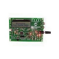
BOARD DEMO FOR MCP3421
Manufacturer
Microchip Technology
Datasheets
1.MCP3421A2T-ECH.pdf
(42 pages)
2.MCP3421DM-BFG.pdf
(26 pages)
3.MCP3421A0T-ECH.pdf
(30 pages)
Specifications of MCP3421DM-BFG
Main Purpose
Power Management, Battery Gauge
Utilized Ic / Part
MCP3421
Processor To Be Evaluated
MCP3421
Lead Free Status / RoHS Status
Lead free / RoHS Compliant
Secondary Attributes
-
Embedded
-
Primary Attributes
-
Lead Free Status / RoHS Status
Lead free / RoHS Compliant, Lead free / RoHS Compliant


MCP3421
In read mode, the RDY bit in the configuration byte
indicates the state of the conversion: (a) RDY = 1
indicates that the data bytes that have just been read
were not updated from the previous conversion. (b)
RDY = 0 indicates that the data bytes that have just
been read were updated.
If the configuration byte is read repeatedly by clocking
continuously after the first read (i.e., after the 5th byte
in the 18-bit conversion mode), the state of the RDY bit
indicates whether the device is ready with new
conversion data. See
RDY = 0 means new conversion data is ready for read-
ing. In this case, the user can send a stop bit to exit the
current read operation and send a new read command
to read out updated conversion data. See Figures 5-2
and 5-3 for reading conversion data. The user can
rewrite the configuration byte any time for a new
setting. Tables 5-1 and 5-2 show the examples of the
configuration bit operation.
TABLE 5-1:
TABLE 5-2:
DS22003D-page 12
R/W O/C RDY
R/W O/C RDY
0
0
0
0
1
1
1
1
0
0
1
1
0
0
1
1
0
1
0
1
0
1
0
1
CONFIGURATION BITS FOR
WRITING
CONFIGURATION BITS FOR
READING
No effect if all other bits remain
the same - operation continues
with the previous settings
Initiate One-Shot Conversion
Initiate Continuous Conversion
Initiate Continuous Conversion
New conversion data in One-
Shot conversion mode has been
just read. The RDY bit remains
low until set by a new write
command.
One-Shot Conversion is in
progress, The conversion data is
not updated yet. The RDY bit
stays high.
New conversion data in Continu-
ous Conversion mode has been
just read. The RDY bit changes
to high after this read.
The conversion data in Continu-
ous Conversion mode was
already read. The latest conver-
sion data is not ready. The RDY
bit stays high until a new
conversion is completed.
Figure
Operation
Operation
5-2. For example,
5.3
The MCP3421 device communicates with Master
(microcontroller) through a serial I
Circuit) interface and supports standard (100 kbits/
sec), fast (400 kbits/sec) and high-speed (3.4 Mbits/
sec) modes. The serial I
bus communication protocol using open-drain SCL and
SDA lines.
The MCP3421 can only be addressed as a slave. Once
addressed, it can receive configuration bits or transmit
the latest conversion results. The serial clock pin (SCL)
is an input only and the serial data pin (SDA) is
bidirectional. An example of a hardware connection
diagram is shown in
The Master starts communication by sending a START
bit and terminates the communication by sending a
STOP bit. The first byte after the START bit is always
the address byte of the device, which includes the
device code, the address bits, and the R/W bit. The
device code for the MCP3421 device is 1101. The
address bits (A2, A1, A0) are pre-programmed at the
factory. In general, the address bits are specified by the
customer when they order the device. The three
address bits are programmed to “000” at the factory, if
they are not specified by the customer.
shows the details of the MCP3421 address byte.
During a low power standby mode, SDA and SCL pins
remain at a floating condition.
More details of the I
in Section 5.6 “I
5.3.1
The address byte is the first byte received following the
START condition from the Master device. The
MCP3421 device code is 1101. The device code is
followed by three address bits (A2, A1, A0) which are
programmed at the factory. The three address bits
allow up to eight MCP3421 devices on the same data
bus line. The (R/W) bit determines if the Master device
wants to read the conversion data or write to the
Configuration register. If the (R/W) bit is set (read
mode), the MCP3421 outputs the conversion data in
the following clocks. If the (R/W) bit is cleared (write
mode), the MCP3421 expects a configuration byte in
the following clocks. When the MCP3421 receives the
correct address byte, it outputs an acknowledge bit
after the R/W bit.
address byte. See Figures 5-2 and 5-3 for the read and
write operations of the device.
I
2
C Serial Communications
DEVICE ADDRESSING
2
C Bus Characteristics”.
2
Figure 5-1
Figure
C bus characteristic is described
2
© 2007 Microchip Technology Inc.
C is a bidirectional 2-wire data
6-1.
shows the MCP3421
2
C (Inter-Integrated
Figure 5-1
Related parts for MCP3421DM-BFG
Image
Part Number
Description
Manufacturer
Datasheet
Request
R

Part Number:
Description:
18-Bit Analog-to-Digital Converter with I2C Interface and On-Board Reference
Manufacturer:
Microchip Technology
Datasheet:

Part Number:
Description:
Manufacturer:
Microchip Technology Inc.
Datasheet:
Part Number:
Description:
Manufacturer:
Microchip Technology Inc.
Datasheet:
Part Number:
Description:
Manufacturer:
Microchip Technology Inc.
Datasheet:
Part Number:
Description:
Manufacturer:
Microchip Technology Inc.
Datasheet:
Part Number:
Description:
Manufacturer:
Microchip Technology Inc.
Datasheet:
Part Number:
Description:
Manufacturer:
Microchip Technology Inc.
Datasheet:
Part Number:
Description:
Manufacturer:
Microchip Technology Inc.
Datasheet:
Part Number:
Description:
Manufacturer:
Microchip Technology Inc.
Datasheet: