ATA6826-DK Atmel, ATA6826-DK Datasheet - Page 15
ATA6826-DK
Manufacturer Part Number
ATA6826-DK
Description
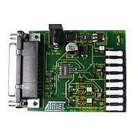
BOARD EVALUATION FOR ATA6826
Manufacturer
Atmel
Specifications of ATA6826-DK
Main Purpose
Power Management, Half H-Bridge Driver (Internal FET)
Embedded
No
Utilized Ic / Part
ATA6826
Primary Attributes
3 Half H-Bridge Drivers, 1A, 2 kV ESD Protection
Secondary Attributes
Short-Circuit, Thermal & Undervoltage Protection
Lead Free Status / RoHS Status
Contains lead / RoHS non-compliant


6.2
4981A–AUTO–02/07
Inductive Shutdown
Any driver IC faces a challenge when an inductive load is connected to its outputs, as the energy
stored in the inductance leads to a voltage peak when the load is switched off. An inductive load
connected to the low-side driver outputs causes a voltage peak with positive polarity, while for
the high-side outputs such peak is negative. In order to prevent any damage to the IC’s output
stages, some protective means have to be implemented.
tection circuit of the outputs.
Figure 6-3.
The clamping structures at the output stages limit the voltage peak and provide a path for the
current after switching off. The maximum inductive shutdown energy for ATA6826 is specified as
15 mJ. This value applies for both low-side and high-side outputs. The energy W
inductor L during the switched-on state can be calculated using the following formula:
w
L
=
L
----------------- -
2
I
L
2
Principal Clamping Structure at a Driver Stage
ATA6826
V
OUTy
S
Figure 6-3
illustrates the principal pro-
ATA6826
L
stored in the
15
Related parts for ATA6826-DK
Image
Part Number
Description
Manufacturer
Datasheet
Request
R

Part Number:
Description:
Triple Half-bridge DMOS Output Driver with Serial Input Control
Manufacturer:
ATMEL Corporation
Datasheet:

Part Number:
Description:
MOSFET & Power Driver ICs Triple Half-Bridge Driver
Manufacturer:
Atmel
Datasheet:
Part Number:
Description:
MOSFET & Power Driver ICs Triple Half-Bridge Driver
Manufacturer:
Atmel
Datasheet:

Part Number:
Description:
DEV KIT FOR AVR/AVR32
Manufacturer:
Atmel
Datasheet:
Part Number:
Description:
INTERVAL AND WIPE/WASH WIPER CONTROL IC WITH DELAY
Manufacturer:
ATMEL Corporation
Datasheet:
Part Number:
Description:
Low-Voltage Voice-Switched IC for Hands-Free Operation
Manufacturer:
ATMEL Corporation
Datasheet:
Part Number:
Description:
MONOLITHIC INTEGRATED FEATUREPHONE CIRCUIT
Manufacturer:
ATMEL Corporation
Datasheet:
Part Number:
Description:
AM-FM Receiver IC U4255BM-M
Manufacturer:
ATMEL Corporation
Datasheet:
Part Number:
Description:
Monolithic Integrated Feature Phone Circuit
Manufacturer:
ATMEL Corporation
Datasheet:
Part Number:
Description:
Multistandard Video-IF and Quasi Parallel Sound Processing
Manufacturer:
ATMEL Corporation
Datasheet:
Part Number:
Description:
High-performance EE PLD
Manufacturer:
ATMEL Corporation
Datasheet:
Part Number:
Description:
8-bit Flash Microcontroller
Manufacturer:
ATMEL Corporation
Datasheet: