ATA6826-DK Atmel, ATA6826-DK Datasheet - Page 2
ATA6826-DK
Manufacturer Part Number
ATA6826-DK
Description
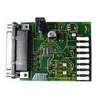
BOARD EVALUATION FOR ATA6826
Manufacturer
Atmel
Specifications of ATA6826-DK
Main Purpose
Power Management, Half H-Bridge Driver (Internal FET)
Embedded
No
Utilized Ic / Part
ATA6826
Primary Attributes
3 Half H-Bridge Drivers, 1A, 2 kV ESD Protection
Secondary Attributes
Short-Circuit, Thermal & Undervoltage Protection
Lead Free Status / RoHS Status
Contains lead / RoHS non-compliant


2.2
Figure 2-1.
2
Features
ATA6826
CLK
INH
DO
CS
DI
Block Diagram
5
6
4
10
9
u.
P
n.
S
F
Output Register
Input Register
• Screwless row connector pins for external loads switched by low-side or high-side drivers
• Easy adaptation of loads directly on the ATA6826 design kit
• Direct switch of loads to V
• Forward/reverse rotation of DC motors by full-bridge application
• Paralleling of outputs for powerful applications
• PC adaptation via standard “SUB-DE” connectors (plug 4 in
• Input for 5V VCC power supply alternatively on board or external by row connector 2
• Indicate rotation direction of DC motors by LEDs, best function at V
• PC-controlled functions via software user interface
• All pins are easily accessible via test points
• Inhibit switch on board or by external input
u.
n.
O
P
Detect
Detect
L
Fault
Fault
OUT3
S
C
D
O
C
S
n.
u.
n.
u.
n.
u.
n.
u.
9
n.
u. u.
n.
u.
Detect
Detect
Fault
Fault
n.
n.
u.
OUT2
n.
u.
Serial Peripheral Interface
u.
n.
n.
u.
u.
n.
H
S
3
H
S
3
12
S
S
L
3
Detect
Detect
S
L
3
Fault
Fault
or GND
H
OUT1
S
2
H
S
2
S
L
2
L
S
2
H
S
1
H
S
1
13
S
L
1
S
L
1
S
R
R
T
P
protection
Control
Thermal
logic
Figure 2-2 on page
protection
Charge
Power-on
pump
Reset
UV
Batt
= 12V
11
14
3
1
7
8
V
V
GND
GND
GND
GND
4981A–AUTO–02/07
S
CC
3)
Related parts for ATA6826-DK
Image
Part Number
Description
Manufacturer
Datasheet
Request
R

Part Number:
Description:
Triple Half-bridge DMOS Output Driver with Serial Input Control
Manufacturer:
ATMEL Corporation
Datasheet:

Part Number:
Description:
MOSFET & Power Driver ICs Triple Half-Bridge Driver
Manufacturer:
Atmel
Datasheet:
Part Number:
Description:
MOSFET & Power Driver ICs Triple Half-Bridge Driver
Manufacturer:
Atmel
Datasheet:

Part Number:
Description:
DEV KIT FOR AVR/AVR32
Manufacturer:
Atmel
Datasheet:
Part Number:
Description:
INTERVAL AND WIPE/WASH WIPER CONTROL IC WITH DELAY
Manufacturer:
ATMEL Corporation
Datasheet:
Part Number:
Description:
Low-Voltage Voice-Switched IC for Hands-Free Operation
Manufacturer:
ATMEL Corporation
Datasheet:
Part Number:
Description:
MONOLITHIC INTEGRATED FEATUREPHONE CIRCUIT
Manufacturer:
ATMEL Corporation
Datasheet:
Part Number:
Description:
AM-FM Receiver IC U4255BM-M
Manufacturer:
ATMEL Corporation
Datasheet:
Part Number:
Description:
Monolithic Integrated Feature Phone Circuit
Manufacturer:
ATMEL Corporation
Datasheet:
Part Number:
Description:
Multistandard Video-IF and Quasi Parallel Sound Processing
Manufacturer:
ATMEL Corporation
Datasheet:
Part Number:
Description:
High-performance EE PLD
Manufacturer:
ATMEL Corporation
Datasheet:
Part Number:
Description:
8-bit Flash Microcontroller
Manufacturer:
ATMEL Corporation
Datasheet: