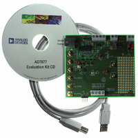
EVAL-AD7877EBZ Analog Devices Inc, EVAL-AD7877EBZ Datasheet - Page 20

EVAL-AD7877EBZ
Manufacturer Part Number
EVAL-AD7877EBZ
Description
BOARD EVALUATION FOR AD7877
Manufacturer
Analog Devices Inc
Datasheets
1.AD7877ACBZ-REEL7.pdf
(44 pages)
2.EVAL-AD7877EBZ.pdf
(16 pages)
3.EVAL-AD7877EBZ.pdf
(44 pages)
Specifications of EVAL-AD7877EBZ
Main Purpose
Interface, Touch Screen Controller
Embedded
No
Utilized Ic / Part
AD7877
Primary Attributes
4-Wire Resistive Touch Screen Controller, SPI Interface, On-Chip: Temp Sensor, Voltage Reference, 8-Bit DAC
Secondary Attributes
USB GUI, LCD Noise Reduction Feature, 2.7 ~ 5.25 V, Wake Up on Touch Feature
Lead Free Status / RoHS Status
Lead free / RoHS Compliant
AD7877
CONTROL REGISTERS
Control Register 1 contains the ADC channel address, the
SER/ DFR bit (to choose single or differential methods of touch
screen measurement), the register read address, and the ADC
mode bits. Control Register 1 should always be the last register
to be programmed prior to starting conversions. Its power-on
default value is 0x00. To change any parameter after conversion
has begun, the part should first be put into Mode 00, the
changes made, and then Control Register 1 reprogrammed,
ensuring that it is always the last register to be programmed
before conversions begin.
11
Control Register 2 sets the timer, reference, polarity, first
conversion delay, averaging, and acquisition time. Its power-on
default value is 0x00. See the Detailed Register Descriptions
section for more information on the control registers.
11
CONTROL REGISTER 1
ADC Mode (Control Register 1, Bits[1:0])
These bits select the operating mode of the ADC. The AD7877
has three operating modes. These are selected by writing to the
mode bits in Control Register 1. If the mode bits are 00, no
conversion is performed.
Table 5. Control Registera 1 Mode Selection
MODE1
0
0
1
1
If the mode bits are 01, a single conversion is performed on the
channel selected by writing to the channel bits of Control
Register 1 (Bit 7 to Bit 10). At the end of the conversion, if the
TMR bits in Control Register 2 are set to 00, the mode bits
revert to 00 and the ADC returns to no convert mode until a
new conversion is initiated by the host. Setting the TMR bits to
a value other than 00 causes the conversion to be repeated, as
described in the Timer (Control Register 2, Bits[1:0]) section.
The flowchart in Figure 38 shows how the AD7877 operates in
Mode 01.
SER/
DFR
AVG
1
CHNL
ADD
AVG
3
0
CHNL
ACQ
ADD
2
1
MODE0
0
1
0
1
CHNL
ADD
ACQ
1
0
Figure 35. Control Register 1
Figure 36. Control Register 2
CHNL
ADD
PM
0
1
Function
Do not convert (default)
Single-channel conversion, AD7877 in
slave mode
Sequence 0, AD7877 in slave mode
Sequence 1, AD7877 in master mode
ADD
RD
PM
4
0
ADD
FCD
RD
3
1
ADD
FCD
RD
2
0
ADD
POL
RD
1
ADD
REF
RD
0
MODE
ADC
TMR
1
1
MODE
ADC
TMR
0
0
Rev. C | Page 20 of 44
0
0
The AD7877 can also be programmed to convert a sequence of
selected channels automatically. The two modes for this type of
conversion are slave mode and master mode.
For slave mode operation, the channels to be digitized are
selected by setting the corresponding bits in Sequencer
Register 0. Conversion is initiated by writing 10b to the mode
bits of Control Register 1. The ADC then digitizes the selected
channels and stores the results in the corresponding results
registers. At the end of the conversion, if the TMR bits in
Control Register 2 are set to 00, the mode bits revert to 00 and
the ADC returns to no convert mode until a new conversion is
initiated by the host. Setting the TMR bits to a code other than
00 causes the conversion sequence to be repeated. The
flowchart in Figure 39 shows how the AD7877 operates in
Mode 10.
For master mode operation, the channels to be digitized are
written to Sequencer Register 1. Master mode is then selected
by writing 11 to the mode bits in Control Register 1. In this
mode, the wake-up on touch feature is active, so conversion
does not begin immediately. The AD7877 waits until the screen
is touched before beginning the sequence of conversions. The
ADC then digitizes the selected channels, and the results are
written to the results registers. The AD7877 waits for the screen
to be touched again, or for a timer event if the screen remains
touched, before beginning another sequence of conversions.
The flowchart in Figure 40 shows how the AD7877 operates in
Mode 11.
ADC Channel (Control Register 1, Bits[10:7])
The ADC channel is selected by Bits [10:7] of Control Register 1
(CHADD3 to CHADD0). In addition, the SER/ DFR bit, Bit 11,
selects between single-ended and differential conversion. A
complete list of channel addresses is given in
For Mode 0 (single-channel) conversion, the channel is selected
by writing the appropriate CHADD3 to CHADD0 code to
Control Register 1.
For sequential channel conversion, channels to be converted are
selected by setting bits corresponding to the channel number in
Sequencer Register 1 for slave mode sequencing or Sequencer
Register 2 for master mode sequencing.
For both single-channel and sequential conversion, normal
(single-ended) conversion is selected by clearing the SER/ DFR
bit in Control Register 1. Ratiometric (differential) conversion
is selected by setting the SER/ DFR bit.
Table 6
.


