EVAL-AD7877EBZ Analog Devices Inc, EVAL-AD7877EBZ Datasheet - Page 35
EVAL-AD7877EBZ
Manufacturer Part Number
EVAL-AD7877EBZ
Description
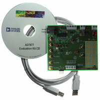
BOARD EVALUATION FOR AD7877
Manufacturer
Analog Devices Inc
Datasheets
1.AD7877ACBZ-REEL7.pdf
(44 pages)
2.EVAL-AD7877EBZ.pdf
(16 pages)
3.EVAL-AD7877EBZ.pdf
(44 pages)
Specifications of EVAL-AD7877EBZ
Main Purpose
Interface, Touch Screen Controller
Embedded
No
Utilized Ic / Part
AD7877
Primary Attributes
4-Wire Resistive Touch Screen Controller, SPI Interface, On-Chip: Temp Sensor, Voltage Reference, 8-Bit DAC
Secondary Attributes
USB GUI, LCD Noise Reduction Feature, 2.7 ~ 5.25 V, Wake Up on Touch Feature
Lead Free Status / RoHS Status
Lead free / RoHS Compliant


DETAILED REGISTER DESCRIPTIONS
Register Name: Control Register 1
Write Address:
Read Address:
Default Value:
Type:
Table 16.
Bit
0
1
2
3
4
5
6
7
8
9
10
11
Name
MODE0
MODE1
RD0
RD1
RD2
RD3
RD4
CHADD0
CHADD1
CHADD2
CHADD3
SER/DFR
Read/Write
R/W
R/W
R/W
R/W
R/W
R/W
R/W
R/W
R/W
R/W
R/W
R/W
0001
00001
0x000
Read/write
Description
LSB of ADC mode code
MSB of ADC mode code
00 = no conversion
01 = single conversion
10 = conversion sequence (slave mode)
11 = conversion sequence (master mode)
LSB of register read address; to read a register, its address must first be written to Control Register 1
Bit 1 of register read address; to read a register, its address must first be written to Control Register 1
Bit 2 of register read address; to read a register, its address must first be written to Control Register 1
Bit 3 of register read address; to read a register, its address must first be written to Control Register 1
MSB of register read address; to read a register, its address must first be written to Control Register 1
LSB of ADC channel address
Bit 1 of ADC channel address
Bit 2 of ADC channel address
MSB of ADC channel address
0000 = X+ input (Y position)
0001 = Y+ input (X position)
0010 = Y− (Z2) input (used for touch-pressure calculation)
0011 = Auxiliary Input 1 (AUX1)
0100 = Auxiliary Input 2 (AUX2)
0101 = Auxiliary Input 3 (AUX3)
0110 = Battery Monitor Input 1 (BAT1)
0111 = Battery Monitor Input 2 (BAT2)
1000 = Temperature Measurement 1 (used for single conversion)
1001 = Temperature Measurement 2 (used for differential measurement method)
1010 = X+ (Z1) input (used for touch-pressure calculation)
Selects normal (single-ended) or ratiometric (differential) conversion
0 = ratiometric (differential)
1 = normal (single-ended)
Rev. C | Page 35 of 44
AD7877
Related parts for EVAL-AD7877EBZ
Image
Part Number
Description
Manufacturer
Datasheet
Request
R


Part Number:
Description:
BOARD EVAL FOR SI270X-A
Manufacturer:
Silicon Laboratories Inc
Datasheet:

Part Number:
Description:
BUCK CONV REF DESIGN KIT IP1201
Manufacturer:
International Rectifier
Datasheet:
Part Number:
Description:
BOARD DEMO SYNC DUAL BUCK CNVTER
Manufacturer:
International Rectifier
Datasheet:
Part Number:
Description:
BOARD DEMO SYNC BUCK CONVETER
Manufacturer:
International Rectifier
Datasheet:

Part Number:
Description:
EVALBOARD/EB Omnidirectional microphone - Analog
Manufacturer:
Analog Devices
Datasheet:
Part Number:
Description:
EVALBOARD/EB Omnidirectional microphone - Analog
Manufacturer:
Analog Devices
Datasheet:


Part Number:
Description:
BOARD EVAL LED DRIVER LT3756
Manufacturer:
Linear Technology
Datasheet:

Part Number:
Description:
BOARD EVAL FOR AD7741/7742
Manufacturer:
Analog Devices Inc
Datasheet:

Part Number:
Description:
±1.7g Dual-Axis IMEMS Accelerometer Evaluation Board
Manufacturer:
Analog Devices Inc
Datasheet:

Part Number:
Description:
IC MULTIPLIER ANALOG 8-SOIC T/R
Manufacturer:
Analog Devices Inc
Datasheet:

Part Number:
Description:
IC ANALOG MULTIPLIER 8-DIP
Manufacturer:
Analog Devices Inc
Datasheet:
Part Number:
Description:
IC ANALOG MULTIPLIER 8-SOIC
Manufacturer:
Analog Devices Inc
Datasheet:
Part Number:
Description:
IC ANALOG MULTIPLIER 8-DIP
Manufacturer:
Analog Devices Inc
Datasheet: